DE2F3KH103MA3B Murata Electronics North America, DE2F3KH103MA3B Datasheet - Page 2
DE2F3KH103MA3B
Manufacturer Part Number
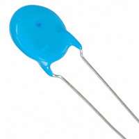
DE2F3KH103MA3B
Description
CAP 10000PF 250VAC F X1Y2 RAD
Manufacturer
Murata Electronics North America
Series
KHr
Datasheets
1.DEBB33A681KA2B.pdf
(72 pages)
2.DE2B3KY221KA2BM01.pdf
(1 pages)
3.DE2B3KY221KA2BM01.pdf
(4 pages)
Specifications of DE2F3KH103MA3B
Capacitance
10000pF
Voltage - Rated
250VAC
Tolerance
±20%
Temperature Coefficient
F
Mounting Type
Through Hole
Operating Temperature
-25°C ~ 85°C
Applications
Safety
Ratings
X1Y2
Package / Case
Radial - Disc
Size / Dimension
0.630" Dia (16mm)
Thickness
7.00mm Max
Lead Spacing
0.295" (7.50mm)
Lead Style
Straight
Lead Free Status / RoHS Status
Lead free / RoHS Compliant
Features
-
Other names
490-4217


No.
10
11
12
13
*
*
9
1
2
"C" expresses nominal capacitance value (pF).
"room condition" Temperature: 15 to 35 C, Relative humidity: 45 to 75%, Atmospheric pressure: 86 to 106kPa
Continued from the preceding page.
Soldering
Effect
(Non-Preheat)
Soldering
Effect
(On-Preheat)
Vibration
Resistance
Humidity
(Under
Steady
State)
Humidity
Loading
Safety Standard Certified Type KY/KH/KX Specifications and Test Methods
Item
Appearance
Capacitance
Change
I.R.
Dielectric
Strength
Appearance
Capacitance
Change
I.R.
Dielectric
Strength
Appearance
Capacitance
D.F.
Q
Appearance
Capacitance
Change
D.F.
Q
I.R.
Dielectric
Strength
Appearance
Capacitance
Change
D.F.
Q
I.R.
Dielectric
Strength
No marked defect
Within 10%
1000M min.
Per Item 6
No marked defect
Within 10%
1000M min.
Per Item 6
No marked defect
Within the specified tolerance
No marked defect
3000M min.
Per Item 6
No marked defect
3000M min.
Per Item 6
Char.
Char.
Char.
Char.
Char.
B, E
E, F
B, E
E, F
B, E
SL
SL
SL
SL
SL
F
B
F
B
F
QU275+5/2C*
QU350
QU275+5/2C*
QU350
QU400+20C*
QU1000
Capacitance Change
Capacitance Change
Specifications
Specifications
Specifications
Specifications
Within 10%
Within 15%
Within
Within 10%
Within 15%
Within
D.F.V2.5%
D.F.V5.0%
D.F.V5.0%
D.F.V7.5%
D.F.V5.0%
D.F.V7.5%
1
1
1
(CF30pF)
(CU30pF)
(CF30pF)
(CU30pF)
(CF30pF)
(CU30pF)
5%
5%
As shown in figure, the lead wires
should be immersed in solder of
350 10 C or 260 5 C up to 1.5
to 2.0mm from the root of terminal
for 3.5 0.5 sec. (10 1 sec. for
260 5 C).
Pre-treatment:
Post-treatment:
First the capacitor should be
stored at 120+0/-5 C for
60+0/-5 sec.
Then, as in figure, the lead wires
should be immersed in solder of
260+0/-5 C up to 1.5 to 2.0mm
from the root of terminal for
7.5+0/-1 sec.
Pre-treatment:
Post-treatment:
The capacitor should be firmly soldered to the supporting lead
wire and vibrated at a frequency range of 10 to 55Hz, 1.5mm in
total amplitude, with about a 1 minute rate of vibration change
from 10Hz to 55Hz and back to 10Hz.
Apply for a total of 6 hrs., 2 hrs. each in 3 mutually
perpendicular directions.
Set the capacitor for 500 12 hrs. at 40 2 C in 90 to 95%
relative humidity.
Post-treatment:
Apply the rated voltage for 500 12 hrs. at 40 2 C in 90 to 95%
relative humidity.
Post-treatment:
Capacitor should be stored at 85 2 C for 1 hr., then placed at
room condition*
Capacitor should be stored for 1 to 2 hrs. at room condition*
Capacitor should be stored at 85 2 C for 1 hr., then placed at
room condition*
Capacitor should be stored for 1 to 2 hrs. at room condition*
Capacitor should be stored for 1 to 2 hrs. at room condition*
Capacitor should be stored for 1 to 2 hrs. at room condition*
2
2
for 24 2 hrs. before initial measurements.
for 24 2 hrs. before initial measurements.
Test Method
Continued on the following page.
Thermal
Screen
Thermal
Screen
Capacitor
Capacitor
Molten
Solder
Molten
Solder
1.5
to 2.0mm
1.5
to 2.0mm
2
2
2
2
.
.
.
.
Related parts for DE2F3KH103MA3B
Image
Part Number
Description
Manufacturer
Datasheet
Request
R

Part Number:
Description:
BUZZER PIEZO 25VP-P SMD
Manufacturer:
Murata Electronics North America

Part Number:
Description:
CAP 4-ARRAY 680PF 100V X7R 1206
Manufacturer:
Murata Electronics North America
Datasheet:
Part Number:
Description:
CAP 4-ARRAY 1000PF 100V X7R 1206
Manufacturer:
Murata Electronics North America
Datasheet:
Part Number:
Description:
CAP 4-ARRAY 1800PF 100V X7R 1206
Manufacturer:
Murata Electronics North America
Datasheet:
Part Number:
Description:
CAP 4-ARRAY 68000PF 16V X7R 1206
Manufacturer:
Murata Electronics North America
Datasheet:

Part Number:
Description:
CAP CER 1000PF 50V 10% X7R 0402
Manufacturer:
Murata Electronics North America
Datasheet:
Part Number:
Description:
CAP CER 10000PF 16V 10% X7R 0402
Manufacturer:
Murata Electronics North America
Datasheet:

Part Number:
Description:
CAP 5.5-25PF 2.5X3.2MM SMD
Manufacturer:
Murata Electronics North America
Datasheet:

Part Number:
Description:
CAP 4.5-20PF 2.5X3.2MM SMD
Manufacturer:
Murata Electronics North America
Datasheet:

Part Number:
Description:
CAP 5.0-20PF 3.2X4.5MM SMD RED
Manufacturer:
Murata Electronics North America
Datasheet:

Part Number:
Description:
CAP 2.0-6.0PF 3.2X4.5MM SMD BLU
Manufacturer:
Murata Electronics North America
Datasheet:

Part Number:
Description:
CAP 1.4-3.0PF 3.2X4.5MM SMD BRN
Manufacturer:
Murata Electronics North America
Datasheet:

Part Number:
Description:
CAP 3.0-10PF 3.2X4.5MM SMD WHT
Manufacturer:
Murata Electronics North America
Datasheet:

Part Number:
Description:
CAP 2.0-6.0PF 4X4.5MM TOPADJ BLU
Manufacturer:
Murata Electronics North America
Datasheet:

Part Number:
Description:
CAP 8.5-40PF 4X4.5MM TOPADJ YEL
Manufacturer:
Murata Electronics North America
Datasheet: