ST203C686MAJ03 AVX Corporation, ST203C686MAJ03 Datasheet - Page 84
ST203C686MAJ03
Manufacturer Part Number
ST203C686MAJ03
Description
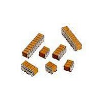
CAP CER 68UF 25V STACKED SMD
Manufacturer
AVX Corporation
Series
TurboCap™r
Specifications of ST203C686MAJ03
Capacitance
68µF
Tolerance
±20%
Temperature Coefficient
X7R
Voltage - Rated
25V
Mounting Type
Surface Mount, MLCC
Operating Temperature
-55°C ~ 125°C
Features
Stacked
Applications
Filtering Switch Mode Power Supplies
Package / Case
6-Stacked SMD, J-Lead
Size / Dimension
0.325" L x 0.300" W (8.26mm x 7.62mm)
Thickness
5.59mm Max
Lead Style
J-Lead
Voltage Rating
25 Volts
Operating Temperature Range
- 55 C to + 125 C
Product
General Type MLCCs
Dielectric Characteristic
X7R
Capacitance Tolerance
± 20%
Capacitor Case Style
DIP
No. Of Pins
6
Capacitor Mounting
SMD
Rohs Compliant
No
Termination Style
Radial
Lead Spacing
6.35 mm
Dimensions
7.62 mm W x 8.26 mm L x 5.59 mm H
Dissipation Factor Df
2.5
Lead Free Status / RoHS Status
Contains lead / RoHS non-compliant
Ratings
-
Lead Spacing
-
Lead Free Status / RoHS Status
Contains lead / RoHS non-compliant
Other names
478-6117


Surface Mounting Guide
Recommended Soldering Profiles
REFLOW SOLDER PROFILES
AVX RoHS compliant products utilize termination
finishes (e.g.Sn or SnAg) that are compatible
with all Pb-Free soldering systems and are fully
reverse compatible with SnPb soldering systems.
A recommended SnPb profile is shown for com-
parison; for Pb-Free soldering, IPC/JEDECJ-STD-
020C may be referenced. The upper line in the
chart shows the maximum envelope to which
products are qualified (typically 3x reflow cycles
at
recommended profile for optimum wettability and
soldering in Pb-Free Systems.
Preheat:
The pre-heat stabilizes the part and reduces the temperature
differential prior to reflow. The initial ramp to 125ºC may be
rapid, but from that point (2-3)ºC/sec is recommended to
allow ceramic parts to heat uniformly and plastic
encapsulated parts to stabilize through the glass transition
temperature of the body (~ 180ºC).
Reflow:
In the reflow phase, the maximum recommended time
> 230ºC is 40secs. Time at peak reflow is 10secs max.;
optimum reflow is achieved at 250ºC, (see wetting balance
chart opposite) but products are qualified to 260ºC max.
Please reference individual product datasheets for
maximum limits
Cool Down:
Cool down should not be forced and 6ºC/sec is recom-
mended. A slow cool down will result in a finer grain
structure of the reflow solder in the solder fillet.
WAVE SOLDER PROFILES
For wave solder, there is no change in the recommended
wave profile; all standard Pb-Free (SnCu/SnCuAg) systems
operate at the same 260ºC max recommended for SnPb
systems.
Preheat:
This is more important for wave solder; a higher temperature
preheat will reduce the thermal shock to SMD parts that are
immersed (please consult individual product data sheets for
SMD parts that are suited to wave solder). SMD parts should
ideally be heated from the bottom-Side prior to wave.
PTH (Pin through hole) parts on the topside should not be
separately heated.
Wave:
250ºC – 260ºC recommended for optimum solderability.
Cool Down:
As with reflow solder, cool down should not be forced and
6ºC/sec is recommended. Any air knives at the end of the
2nd wave should be heated.
260ºC max). The center line gives the
275
250
225
200
175
150
125
100
75
50
25
0
20
40
IMPORTANT NOTE: Typical Pb-Free reflow solders have a
more dull and grainy appearance compared to traditional
SnPb. Elevating the reflow temperature will not change this,
but extending the cool down can help improve the visual
appearance of the joint.
Maximum Reflow Profile With Care
Recommended Pb-Free Reflow Profile
Recommended SnPb Reflow Profile
-0.10
-0.20
-0.30
-0.40
60
0.40
0.30
0.20
0.10
0.00
200
80
275
225
175
125
75
25
100
0
Preheat
Wetting Force at 2nd Sec. (higher is better)
210
120
Preheat
Preheat
Temperature of Solder [C]
Preheat
50
Recommended Reflow Profiles
140
Preheat
Preheat
220
Preheat
160
Preheat
Recommended Soldering Profiles
100
230
180
Wave
Time / secs
200
150
240
Wave
Time / seconds
Cool Down
220
Reflow
Reflow
Wave
Wave
240
200
250
Cool Down
260
Reflow
Cool Down
260
280
250
Reflow
300
270
Cool Down
Cool Down
300
320
340
350
Cool Down
360
SnPb - Sn60Pb40
Sn - Sn60Pb40
Sn-Sn3.5Ag0.7Cu
Sn-Sn2.5Ag1Bi0.5Cu
Sn-Sn0.7Cu
380
Cool Down
400
400
83
420
Related parts for ST203C686MAJ03
Image
Part Number
Description
Manufacturer
Datasheet
Request
R

Part Number:
Description:
Inverter Grade Thyristors
Manufacturer:
International Rectifier Corp.
Datasheet:

Part Number:
Description:
Manufacturer:
AVX Corporation
Datasheet:
Part Number:
Description:
Manufacturer:
AVX Corporation
Datasheet:
Part Number:
Description:
Manufacturer:
AVX Corporation
Datasheet:
Part Number:
Description:
Manufacturer:
AVX Corporation
Datasheet: