MBR2030CT Diodes Inc, MBR2030CT Datasheet
MBR2030CT
Specifications of MBR2030CT
Available stocks


Related parts for MBR2030CT


MBR2030CT Summary of contents
Page 1
... Thermal resistance junction to case mounted on heatsink. 2. Measured at 1.0MHz and applied reverse voltage of 4.0V DC. 3. Pulse width £300 ms, duty cycle £2%. 4. RoHS revision 13.2.2003. Glass and High Temperature Solder Exemptions Applied, see EU Directive Annex Notes 5 and 7 . DS23016 Rev MBR2030CT - MBR2060CT 20A SCHOTTKY BARRIER RECTIFIER ...
Page 2
... PERCENT OF RATED PEAK REVERSE VOLTAGE (%) Fig. 5 Typical Reverse Characteristics www.diodes.com MBR 2030CT - MBR 2045CT MBR 2050CT - MBR 2060CT 0.2 0.4 0.6 0.8 Fig. 2 Typical Forward Characteristics 1 REVERSE VOLTAGE (V) R Fig. 4 Typical Total Capacitance (per element) 120 140 MBR2030CT - MBR2060CT 1.0 100 ...
Page 3
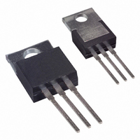
... Ordering Information Device MBR20xxCT Device type, e.g. MBR2045CT Notes: 5. For Packaging Details our website at http://www.diodes.com/datasheets/ap02007.pdf. DS23016 Rev Packaging TO-220AB www.diodes.com Shipping 50/Tube MBR2030CT - MBR2060CT ...