STTH1R02 STMicroelectronics, STTH1R02 Datasheet
STTH1R02
Specifications of STTH1R02
Available stocks


Related parts for STTH1R02


STTH1R02 Summary of contents
Page 1
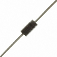
... Low forward and reverse recovery times ■ High junction temperature Description The STTH1R02 uses ST's new 200 V planar Pt doping technology, and it is specially suited for switching mode base drive and transistor circuits. Packaged in DO-41, DO-15, SMA, and SMB, this device is intended for use in low voltage, high frequency inverters, free wheeling and polarity protection ...
Page 2
... Lead Length = infinite heatsink Test conditions T = 25° 125° 25° 4 25° 100° 1 150° (RMS) STTH1R02 Value 200 = 5 µ kHz 110° C lead = 110° C lead 1.5 = 110° 110° - 175 175 Value DO-41 45 DO-15 45 SMA 30 SMB 30 Min. Typ Max. 3 ...
Page 3
... STTH1R02 Table 4. Dynamic characteristics Symbol Parameter t Reverse recovery time rr I Reverse recovery current RM t Forward recovery time fr V Forward recovery voltage FP Figure 1. Peak current versus duty cycle δ 0 0.0 0.1 0.2 0.3 0.4 0.5 Figure 3. Forward voltage drop versus forward current (maximum values) ...
Page 4
... DO-41 Lleads=10mm Single pulse 1.E-02 1.E-01 1.E+00 1.E+01 1.E+02 Junction capacitance versus reverse applied voltage (typical values 100 (typical values) T =125° =25°C j 100 STTH1R02 t (s) P 1.E+03 F=1MHz =30mV osc RMS T =25° (V) R 1000 / =1. =160V R dI /dt(A/µ ...
Page 5
... STTH1R02 Figure 11. Peak reverse recovery curent versus dI /dt (typical values =1. =160V =125° 100 Figure 13. Thermal resistance, junction to ambient, versus copper surface under each lead - SMA (Epoxy FR4, copper thickness = 35 µm) 120 100 Figure 15. Thermal resistance, junction to ambient, versus copper surface under each lead - DO 15 (Epoxy FR4, copper thickness = 35 µ ...
Page 6
... RL = DO-41 in Tape and reel A = SMA in Tape and reel Q = DO-15 in Ammopack QRL = DO-15 in Tape and reel U = SMB in Tape and reel Ref. ØD Ø Ref STTH1R02 Dimensions Millimeters Inches Min. Max. Min. Max. 4.1 5.20 0.160 0.205 2 2.71 0.080 0.107 25.4 1 0.712 0.863 ...
Page 7
... STTH1R02 Table 7. SMA dimensions Figure 17. SMA footprint (dimensions in mm) REF. Millimeters Min. A1 1.90 A2 0.05 b 1.25 c 0.15 E 4.80 E1 3.95 D 2.25 L 0.75 1.73 1.48 1.73 1.67 4.94 Package information DIMENSIONS Inches Max. Min. Max. 2.03 0.075 0.080 0.20 0.002 0.008 1.65 0.049 0.065 ...
Page 8
... Millimeters Inches Min. Max. Min. 1.90 2.45 0.075 0.05 0.20 0.002 1.95 2.20 0.077 0.15 0.41 0.006 5.10 5.60 0.201 4.05 4.60 0.159 3.30 3.95 0.130 0.75 1.60 0.030 2.23 2.30 STTH1R02 Max. 0.096 0.008 0.087 0.016 0.220 0.181 0.156 0.063 ...
Page 9
... STTH1R02 4 Ordering information Part Number STTH1R02 STTH1R02RL STTH1R02A STTH1R02Q STTH1R02QRL STTH1R02U 5 Revision history Date 03-May-2006 13-Oct-2006 08-Mar-2007 Marking Package STTH1R02 DO-41 STTH1R02 DO-41 R1A SMA STTH1R02Q DO-15 STTH1R02Q DO-15 1R2S SMB Revision 1 First issue 2 Added DO-15 and SMB packages. 3 Replaced Figure 8. Replaced e ...
Page 10
... Australia - Belgium - Brazil - Canada - China - Czech Republic - Finland - France - Germany - Hong Kong - India - Israel - Italy - Japan - Malaysia - Malta - Morocco - Singapore - Spain - Sweden - Switzerland - United Kingdom - United States of America 10/10 Please Read Carefully: © 2007 STMicroelectronics - All rights reserved STMicroelectronics group of companies www.st.com STTH1R02 ...