C8051F560-IQ Silicon Laboratories Inc, C8051F560-IQ Datasheet - Page 95
C8051F560-IQ
Manufacturer Part Number
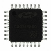
C8051F560-IQ
Description
IC 8051 MCU 32K FLASH 32-QFP
Manufacturer
Silicon Laboratories Inc
Series
C8051F56xr
Specifications of C8051F560-IQ
Program Memory Type
FLASH
Program Memory Size
32KB (32K x 8)
Package / Case
32-QFP
Core Processor
8051
Core Size
8-Bit
Speed
50MHz
Connectivity
SMBus (2-Wire/I²C), CAN, LIN, SPI, UART/USART
Peripherals
POR, PWM, Temp Sensor, WDT
Number Of I /o
25
Ram Size
2.25K x 8
Voltage - Supply (vcc/vdd)
1.8 V ~ 5.25 V
Data Converters
A/D 25x12b
Oscillator Type
Internal
Operating Temperature
-40°C ~ 125°C
Processor Series
C8051F5x
Core
8051
Data Bus Width
8 bit
Data Ram Size
2304 B
Maximum Clock Frequency
50 MHz
Number Of Programmable I/os
25
Operating Supply Voltage
1.8 V to 5.25 V
Maximum Operating Temperature
+ 125 C
Mounting Style
SMD/SMT
3rd Party Development Tools
PK51, CA51, A51, ULINK2
Development Tools By Supplier
C8051F560DK
Minimum Operating Temperature
- 40 C
Lead Free Status / RoHS Status
Lead free / RoHS Compliant
For Use With
336-1691 - KIT DEVELOPMENT FOR C8051F560
Eeprom Size
-
Lead Free Status / Rohs Status
Lead free / RoHS Compliant
Other names
336-1693
Available stocks
Company
Part Number
Manufacturer
Quantity
Price
Company:

Part Number:
C8051F560-IQ
Manufacturer:
Silicon Laboratories Inc
Quantity:
10 000
Company:
Part Number:
C8051F560-IQR
Manufacturer:
Silicon Laboratories Inc
Quantity:
10 000


C8051F55x/56x/57x
12. Special Function Registers
The direct-access data memory locations from 0x80 to 0xFF constitute the special function registers
(SFRs). The SFRs provide control and data exchange with the C8051F55x/56x/57x's resources and
peripherals. The CIP-51 controller core duplicates the SFRs found in a typical 8051 implementation as well
as implementing additional SFRs used to configure and access the sub-systems unique to the
C8051F55x/56x/57x. This allows the addition of new functionality while retaining compatibility with the
MCS-51™ instruction set. Table 12.3 lists the SFRs implemented in the C8051F55x/56x/57x device family.
The SFR registers are accessed anytime the direct addressing mode is used to access memory locations
from 0x80 to 0xFF. SFRs with addresses ending in 0x0 or 0x8 (e.g., P0, TCON, SCON0, IE, etc.) are bit-
addressable as well as byte-addressable. All other SFRs are byte-addressable only. Unoccupied
addresses in the SFR space are reserved for future use. Accessing unoccupied addresses in the SFR
space will have an indeterminate effect and should be avoided. Refer to the corresponding pages of the
data sheet, as indicated in Table 12.3, for a detailed description of each register.
12.1. SFR Paging
The CIP-51 features SFR paging , allowing the device to map many SFRs into the 0x80 to 0xFF memory
address space. The SFR memory space has 256 pages . In this way, each memory location from 0x80 to
0xFF can access up to 256 SFRs. The C8051F55x/56x/57x family of devices utilizes three SFR pages:
0x00, 0x0C, and 0x0F. SFR pages are selected using the Special Function Register Page Selection regis-
ter, SFRPAGE (see SFR Definition 11.3). The procedure for reading and writing an SFR is as follows:
1. Select the appropriate SFR page number using the SFRPAGE register.
2. Use direct accessing mode to read or write the special function register (MOV instruction).
12.2. Interrupts and SFR Paging
When an interrupt occurs, the SFR Page Register will automatically switch to the SFR page containing the
flag bit that caused the interrupt. The automatic SFR Page switch function conveniently removes the bur-
den of switching SFR pages from the interrupt service routine. Upon execution of the RETI instruction, the
SFR page is automatically restored to the SFR Page in use prior to the interrupt. This is accomplished via
a three-byte SFR Page Stack . The top byte of the stack is SFRPAGE, the current SFR Page. The second
byte of the SFR Page Stack is SFRNEXT. The third, or bottom byte of the SFR Page Stack is SFRLAST.
Upon an interrupt, the current SFRPAGE value is pushed to the SFRNEXT byte, and the value of
SFRNEXT is pushed to SFRLAST. Hardware then loads SFRPAGE with the SFR Page containing the flag
bit associated with the interrupt. On a return from interrupt, the SFR Page Stack is popped resulting in the
value of SFRNEXT returning to the SFRPAGE register, thereby restoring the SFR page context without
software intervention. The value in SFRLAST (0x00 if there is no SFR Page value in the bottom of the
stack) of the stack is placed in SFRNEXT register. If desired, the values stored in SFRNEXT and SFR-
LAST may be modified during an interrupt, enabling the CPU to return to a different SFR Page upon exe-
cution of the RETI instruction (on interrupt exit). Modifying registers in the SFR Page Stack does not cause
a push or pop of the stack. Only interrupt calls and returns will cause push/pop operations on the SFR
Page Stack.
On the C8051F55x/56x/57x devices, vectoring to an interrupt will switch SFRPAGE to page 0x00, except
for the CAN0 interrupt which will switch SFRPAGE to page 0x0C.
Rev. 1.1
95
Related parts for C8051F560-IQ
Image
Part Number
Description
Manufacturer
Datasheet
Request
R

Part Number:
Description:
SMD/C°/SINGLE-ENDED OUTPUT SILICON OSCILLATOR
Manufacturer:
Silicon Laboratories Inc
Part Number:
Description:
Manufacturer:
Silicon Laboratories Inc
Datasheet:
Part Number:
Description:
N/A N/A/SI4010 AES KEYFOB DEMO WITH LCD RX
Manufacturer:
Silicon Laboratories Inc
Datasheet:
Part Number:
Description:
N/A N/A/SI4010 SIMPLIFIED KEY FOB DEMO WITH LED RX
Manufacturer:
Silicon Laboratories Inc
Datasheet:
Part Number:
Description:
N/A/-40 TO 85 OC/EZLINK MODULE; F930/4432 HIGH BAND (REV E/B1)
Manufacturer:
Silicon Laboratories Inc
Part Number:
Description:
EZLink Module; F930/4432 Low Band (rev e/B1)
Manufacturer:
Silicon Laboratories Inc
Part Number:
Description:
I°/4460 10 DBM RADIO TEST CARD 434 MHZ
Manufacturer:
Silicon Laboratories Inc
Part Number:
Description:
I°/4461 14 DBM RADIO TEST CARD 868 MHZ
Manufacturer:
Silicon Laboratories Inc
Part Number:
Description:
I°/4463 20 DBM RFSWITCH RADIO TEST CARD 460 MHZ
Manufacturer:
Silicon Laboratories Inc
Part Number:
Description:
I°/4463 20 DBM RADIO TEST CARD 868 MHZ
Manufacturer:
Silicon Laboratories Inc
Part Number:
Description:
I°/4463 27 DBM RADIO TEST CARD 868 MHZ
Manufacturer:
Silicon Laboratories Inc
Part Number:
Description:
I°/4463 SKYWORKS 30 DBM RADIO TEST CARD 915 MHZ
Manufacturer:
Silicon Laboratories Inc
Part Number:
Description:
N/A N/A/-40 TO 85 OC/4463 RFMD 30 DBM RADIO TEST CARD 915 MHZ
Manufacturer:
Silicon Laboratories Inc
Part Number:
Description:
I°/4463 20 DBM RADIO TEST CARD 169 MHZ
Manufacturer:
Silicon Laboratories Inc