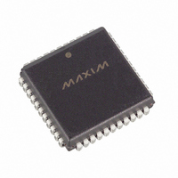
DS80C323-QCD+ Maxim Integrated Products, DS80C323-QCD+ Datasheet - Page 16

DS80C323-QCD+
Manufacturer Part Number
DS80C323-QCD+
Description
IC MCU HI SPEED 18MHZ 44-PLCC
Manufacturer
Maxim Integrated Products
Series
80Cr
Datasheet
1.DS80C323-QND.pdf
(38 pages)
Specifications of DS80C323-QCD+
Core Processor
8051
Core Size
8-Bit
Speed
18MHz
Connectivity
EBI/EMI, SIO, UART/USART
Peripherals
Power-Fail Reset, WDT
Number Of I /o
32
Program Memory Type
ROMless
Ram Size
256 x 8
Voltage - Supply (vcc/vdd)
4.5 V ~ 5.5 V
Oscillator Type
External
Operating Temperature
0°C ~ 70°C
Package / Case
44-LCC, 44-PLCC
Processor Series
DS80C323
Core
8051
Data Bus Width
8 bit
Program Memory Size
64 KB
Data Ram Size
64 KB
Interface Type
UART
Maximum Clock Frequency
18 MHz
Number Of Programmable I/os
32
Number Of Timers
3
Operating Supply Voltage
2.7 V to 5.5 V
Maximum Operating Temperature
+ 70 C
Mounting Style
SMD/SMT
3rd Party Development Tools
PK51, CA51, A51, ULINK2
Minimum Operating Temperature
0 C
Lead Free Status / RoHS Status
Lead free / RoHS Compliant
Eeprom Size
-
Program Memory Size
-
Data Converters
-
Lead Free Status / Rohs Status
Details
a 25MHz crystal frequency. Note that once the counter chain has reached a conclusion, the optional
interrupt is generated. Regardless of whether the user enables this interrupt, there are then 512 clocks left
until a reset occurs. There are 5 control bits in special function registers that affect the Watchdog Timer
and two status flags that report to the user. The Reset Watchdog Timer bit (WDCON.0) should be
asserted prior to modifying the Watchdog Timer Mode Select bits (WD1, WD0) to avoid corruption of
the watchdog count.
WDIF (WDCON.3) is the interrupt flag that is set when there are 512 clocks remaining until a reset
occurs. WTRF (WDCON.2) is the flag that is set when a Watchdog reset has occurred. This allows the
application software to determine the source of a reset.
Setting the EWT (WDCON.1) bit enables the Watchdog Timer. The bit is protected by timed access.
Setting the RWT (WDCON.0) bit restarts the Watchdog Timer for another full interval. Application
software must set this bit prior to the timeout. As mentioned previously, WD1 and 0 (CKCON .7 and 6)
select the timeout. Finally, the Watchdog Interrupt is enabled using EWDI (EIE.4).
INTERRUPTS
The DS80C320/DS80C323 provide 13 sources of interrupt with three priority levels. The Power-fail
Interrupt (PFI), if enabled, always has the highest priority. There are two remaining user-selectable
priorities: high and low. If two interrupts that have the same priority occur simultaneously, the natural
precedence given in Table 4 determines which is acted upon. Except for the PFI, all interrupts that are
new to the 8051 family have a lower natural priority than the originals.
Table 4. Interrupt Priority
SCON0
SCON1
NAME
WDTI
INT2
INT4
INT0
INT1
INT3
INT5
TF0
TF1
TF2
PFI
Power-Fail Interrupt
External Interrupt 0
Timer 0
External Interrupt 1
Timer 1
TI0 or RI0 from Serial Port 0
Timer 2
TI1 or RI1 from Serial Port 1
External Interrupt 2
External Interrupt 3
External Interrupt 4
External Interrupt 5
Watchdog Timeout Interrupt
FUNCTION
DS80C320/DS80C323 High-Speed/Low-Power Microcontrollers
16 of 38
VECTOR
33h
0Bh
1Bh
2Bh
3Bh
4Bh
5Bh
03h
13h
23h
43h
53h
63h
j
NATURAL
PRIORITY
10
11
12
13
1
2
3
4
5
6
7
8
9
OLD/NEW
New
New
New
New
New
New
New
Old
Old
Old
Old
Old
Old


