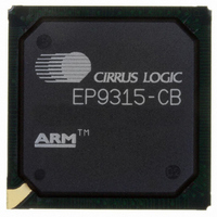
EP9315-CB Cirrus Logic Inc, EP9315-CB Datasheet - Page 414

EP9315-CB
Manufacturer Part Number
EP9315-CB
Description
IC ARM920T MCU 200MHZ 352-PBGA
Manufacturer
Cirrus Logic Inc
Series
EP9r
Specifications of EP9315-CB
Core Processor
ARM9
Core Size
16/32-Bit
Speed
200MHz
Connectivity
EBI/EMI, EIDE, Ethernet, I²C, IrDA, Keypad/Touchscreen, PCMCIA, SPI, UART/USART, USB
Peripherals
AC'97, DMA, I²:S, LCD, LED, MaverickKey, POR, PWM, WDT
Number Of I /o
16
Program Memory Type
ROMless
Ram Size
32K x 8
Voltage - Supply (vcc/vdd)
1.65 V ~ 3.6 V
Data Converters
A/D 8x12b
Oscillator Type
External
Operating Temperature
0°C ~ 70°C
Package / Case
352-BGA
Processor Series
EP93xx
Core
ARM920T
Data Bus Width
32 bit
3rd Party Development Tools
MDK-ARM, RL-ARM, ULINK2
Development Tools By Supplier
EDB9315A-Z
For Use With
598-1144 - KIT DEVELOPMENT EP9315 ARM9
Lead Free Status / RoHS Status
Contains lead / RoHS non-compliant
Eeprom Size
-
Program Memory Size
-
Lead Free Status / Rohs Status
No
Other names
598-1261
Available stocks
Company
Part Number
Manufacturer
Quantity
Price
Part Number:
EP9315-CBZ
Manufacturer:
CIRRUS
Quantity:
20 000
- Current page: 414 of 824
- Download datasheet (13Mb)
10
10-20
DMA Controller
EP93xx User’s Guide
10.2.1 DMA Controller Memory Map
10.2 Registers
During normal operation, using the “fair” rotating priority scheme shown in
channel to be serviced becomes the lowest priority channel with the others rotating
accordingly. In addition, any device requesting service is guaranteed to be recognized after
no more than eleven higher priority services has occurred. This prevents any one channel
from monopolizing the system. When the bus is idle, the scheme reverts to a fixed priority
whereby the highest priority request gets in first (as shown in
resumes to normal operation.
In the case where the two M2M channels are requesting a service, the [PW] size of the read
or write transfers for the first channel are completed before the read transfer for the second
channel begins. See subsections under
handshaking protocols for hardware and software-triggered M2M channel transfers.
Table 10-3
channels (5 Tx and 5 Rx), plus the 2 M2M (memory-to-memory) channels.
Before programming a channel, the clock for that channel must be turned on by setting the
appropriate bit in the PwrCnt register of the Clock and State Controller block.
0x8000_0080 -> 0x8000_00BC
0x8000_00C0 -> 0x8000_00FC
0x8000_0180 -> 0x8000_01BC
0x8000_01C0 -> 0x8000_01FC
0x8000_0280 -> 0x8000_02BC
0x8000_02C0 -> 0x8000_02FC
0x8000_0000 -> 0x8000_003C
0x8000_0040 -> 0x8000_007C
0x8000_0100 -> 0x8000_013C
0x8000_0140 -> 0x8000_017C
0x8000_0200 -> 0x8000_023C
0x8000_0240 -> 0x8000_027C
0x8000_0300 -> 0x8000_033C
ARM920T Address
Lowest
defines the DMA Controller mapping for each of 10 M2P (memory-to-peripheral)
Table 10-2. M2P DMA Bus Arbitration (Continued)
Table 10-3. DMA Memory Map
Copyright 2007 Cirrus Logic
Internal Arbitration Priority
M2P Channel 1 Registers (Rx)
M2P Channel 3 Registers (Rx)
M2P Channel 5 Registers (Rx)
M2P Channel 7 Registers (Rx)
M2P Channel 9 Registers (Rx)
CHARB = 0
M2P Channel 0 Registers (Tx)
M2P Channel 2 Registers (Tx)
M2P Channel 4 Registers (Tx)
M2P Channel 6 Registers (Tx)
M2M Ch 0
M2M Ch 1
M2P Ch 7
M2P Ch 8
M2P Ch 9
M2M Channel 0 Registers
M2M Channel 1 Registers
Description
Not Used
Not Used
Section 10.1.5
for detailed information about
Channel Base Address
Table
CHARB = 1
M2P Ch 5
M2P Ch 6
M2P Ch 7
M2P Ch 8
M2P Ch 9
0x8000_00C0
0x8000_02C0
0x8000_0000
0x8000_0040
0x8000_0080
0x8000_0100
0x8000_0140
0x8000_0200
0x8000_0240
0x8000_0280
0x8000_0300
10-2) when the bus
Table
10-2, the last
DS785UM1
Related parts for EP9315-CB
Image
Part Number
Description
Manufacturer
Datasheet
Request
R

Part Number:
Description:
IC ARM9 SOC ENH UNIV 352PBGA
Manufacturer:
Cirrus Logic Inc
Datasheet:

Part Number:
Description:
32-Bit Microcontroller IC
Manufacturer:
Cirrus Logic Inc
Datasheet:

Part Number:
Description:
IC ARM920T MCU 200MHZ 352-PBGA
Manufacturer:
Cirrus Logic Inc
Datasheet:

Part Number:
Description:
MCU, MPU & DSP Development Tools Eval Bd Uni. ARM9 SOC Processor
Manufacturer:
Cirrus Logic Inc
Datasheet:

Part Number:
Description:
IC ARM920T MCU 166MHZ 208-LQFP
Manufacturer:
Cirrus Logic Inc
Datasheet:

Part Number:
Description:
IC ARM920T MCU 200MHZ 352-PBGA
Manufacturer:
Cirrus Logic Inc
Datasheet:

Part Number:
Description:
IC ARM920T MCU 166MHZ 208-LQFP
Manufacturer:
Cirrus Logic Inc
Datasheet:

Part Number:
Description:
Development Kit
Manufacturer:
Cirrus Logic Inc
Datasheet:

Part Number:
Description:
Development Kit
Manufacturer:
Cirrus Logic Inc
Datasheet:

Part Number:
Description:
High-efficiency PFC + Fluorescent Lamp Driver Reference Design
Manufacturer:
Cirrus Logic Inc
Datasheet:

Part Number:
Description:
Development Kit
Manufacturer:
Cirrus Logic Inc
Datasheet:

Part Number:
Description:
Development Kit
Manufacturer:
Cirrus Logic Inc
Datasheet:

Part Number:
Description:
Development Kit
Manufacturer:
Cirrus Logic Inc
Datasheet:

Part Number:
Description:
Ref Bd For Speakerbar MSA & DSP Products
Manufacturer:
Cirrus Logic Inc


