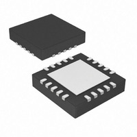
PIC16F785-I/ML Microchip Technology, PIC16F785-I/ML Datasheet - Page 6

PIC16F785-I/ML
Manufacturer Part Number
PIC16F785-I/ML
Description
IC PIC MCU FLASH 2KX14 20QFN
Manufacturer
Microchip Technology
Series
PIC® 16Fr
Datasheets
1.PIC16F616T-ISL.pdf
(8 pages)
2.PIC16F785-ISS.pdf
(206 pages)
3.PIC16F785-ISS.pdf
(10 pages)
4.PIC16F785-ISS.pdf
(28 pages)
Specifications of PIC16F785-I/ML
Core Size
8-Bit
Program Memory Size
3.5KB (2K x 14)
Core Processor
PIC
Speed
20MHz
Peripherals
Brown-out Detect/Reset, POR, PWM, WDT
Number Of I /o
17
Program Memory Type
FLASH
Eeprom Size
256 x 8
Ram Size
128 x 8
Voltage - Supply (vcc/vdd)
2 V ~ 5.5 V
Data Converters
A/D 14x10b
Oscillator Type
Internal
Operating Temperature
-40°C ~ 85°C
Package / Case
20-VQFN Exposed Pad, 20-HVQFN, 20-SQFN, 20-DHVQFN
Controller Family/series
PIC16F
No. Of I/o's
18
Eeprom Memory Size
256Byte
Ram Memory Size
128Byte
Cpu Speed
20MHz
No. Of Timers
3
Lead Free Status / RoHS Status
Lead free / RoHS Compliant
For Use With
AC164322 - MODULE SOCKET MPLAB PM3 28/44QFN
Connectivity
-
Lead Free Status / RoHS Status
Lead free / RoHS Compliant, Lead free / RoHS Compliant
Available stocks
Company
Part Number
Manufacturer
Quantity
Price
Company:
Part Number:
PIC16F785-I/ML
Manufacturer:
Microchip Technology
Quantity:
1 949
PIC16F785/HV785
3.0
Two methods are available to enter Program/Verify
mode. The ‘V
ICSPDAT and ICSPCLK low while raising MCLR pin
from V
data. This method can be used for any Configuration
Word selection and must be used if the INTOSC and
internal MCLR options are selected (FOSC<2:0> = 100
or 101 and MCLRE = 0). The V
the device from executing code prior to entering
Program/Verify mode. See the timing diagram in
Figure 3-1. To prevent the device from executing code
while exiting Program/Verify mode, the ‘V
also be used if the INTOSC and internal MCLR options
are selected. See the timing diagram in Figure 3-3.
The second entry method, ‘V
applying V
then raising MCLR pin from V
followed by data. This method can be used for any
Configuration Word selection except when INTOSC
and
(FOSC<2:0> = 100 or 101 and MCLRE = 0). This
technique is useful when programming the device
when V
disconnect V
See the timing diagram in Figure 3-2.
Once in this mode, the program memory, data memory,
and configuration memory can be accessed and
programmed in serial fashion. ICSPDAT and ICSPCLK
are Schmitt Trigger inputs in this mode.
The sequence that enters the device into the
Programming/Verify mode momentarily places all other
logic into the Reset state (the MCLR pin was initially at
V
impedance inputs) and the Program Counter (PC) is
cleared.
To prevent a device configured with INTOSC and
internal MCLR from executing after exiting Program/
Verify mode, V
See Figure 3-3 for the timing.
DS41237D-page 6
IL
). Therefore, all I/O’s are in the Reset state (high-
IL
internal
DD
to V
PROGRAM/VERIFY MODE
is already applied, for it is not necessary to
DD
IHH
DD
, holding ICSPDAT and ICSPCLK low,
PP
DD
to enter or exit Program/Verify mode.
(high voltage), then applying V
-first’ method is entered by holding
MCLR
needs to power-down before V
options
IL
DD
to V
PP
-first’, is entered by
-first entry prevents
IHH
are
(high voltage),
PP
-last’ must
selected
DD
and
PP
.
FIGURE 3-1:
FIGURE 3-2:
FIGURE 3-3:
ICSPDAT
ICSPCLK
ICSPCLK
Note:
ICSPDAT
Note:
Note:
ICSPDAT
ICSPCLK
V
V
V
V
V
V
DD
PP
DD
PP
DD
PP
This method of entry is not valid if
INTOSC and internal MCLR are selected.
This method must be used if INTOSC
and internal MCLR are selected.
This method of entry is valid, regardless
of Configuration Word selected.
T
T
V
VERIFY MODE ENTRY
V
VERIFY MODE ENTRY
V
VERIFY MODE EXIT
PPDP
HLD
2009 Microchip Technology Inc.
PP
DD
PP
T
HLD
0
-FIRST PROGRAM/
-LAST PROGRAM/
-FIRST PROGRAM/
0
T
T
HLD
PPDP
0


