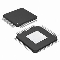
PIC24FJ256DA210-I/PT Microchip Technology, PIC24FJ256DA210-I/PT Datasheet - Page 242

PIC24FJ256DA210-I/PT
Manufacturer Part Number
PIC24FJ256DA210-I/PT
Description
MCU PIC 16BIT FLASH 256K 100TQFP
Manufacturer
Microchip Technology
Series
PIC® 24Fr
Specifications of PIC24FJ256DA210-I/PT
Core Size
16-Bit
Program Memory Size
256KB (85.5K x 24)
Core Processor
PIC
Speed
32MHz
Connectivity
I²C, IrDA, SPI, UART/USART, USB OTG
Peripherals
Brown-out Detect/Reset, GFX, LVD, POR, PWM, WDT
Number Of I /o
84
Program Memory Type
FLASH
Ram Size
96K x 8
Voltage - Supply (vcc/vdd)
2.2 V ~ 3.6 V
Data Converters
A/D 24x10b
Oscillator Type
Internal
Operating Temperature
-40°C ~ 85°C
Package / Case
100-TFQFP
Controller Family/series
PIC24
No. Of I/o's
84
Ram Memory Size
96KB
Cpu Speed
32MHz
No. Of Timers
5
Interface
I2C, SPI, UART, USB
Embedded Interface Type
I2C, SPI, UART, USB
Rohs Compliant
Yes
Processor Series
PIC24FJ
Core
PIC
Data Bus Width
16 bit
Data Ram Size
96 KB
Interface Type
UART, SPI, USB, I2C, RS-485, RS-232
Maximum Clock Frequency
32 MHz
Number Of Programmable I/os
23
Number Of Timers
5
Operating Supply Voltage
3.6 V
Maximum Operating Temperature
+ 85 C
Mounting Style
SMD/SMT
3rd Party Development Tools
52713-733, 52714-737, 53276-922, EWDSPIC
Development Tools By Supplier
PG164130, DV164035, DV244005, DV164005, AC164127-4, AC164127-6, AC164139, DM240001, DM240312, DV164039
Minimum Operating Temperature
- 40 C
Lead Free Status / RoHS Status
Lead free / RoHS Compliant
Eeprom Size
-
Lead Free Status / Rohs Status
Details
Available stocks
Company
Part Number
Manufacturer
Quantity
Price
Company:
Part Number:
PIC24FJ256DA210-I/PT
Manufacturer:
Microchip Technology
Quantity:
10 000
Part Number:
PIC24FJ256DA210-I/PT
Manufacturer:
MICROCHIP/微芯
Quantity:
20 000
- Current page: 242 of 408
- Download datasheet (4Mb)
PIC24FJ256DA210 FAMILY
18.1.2
18.1.2.1
PIC24FJ256DA210 family devices have a built-in
15 k pull-down resistor on the D+ and D- lines. These
are used in tandem to signal to the bus that the micro-
controller is operating in Host mode. They are engaged
by setting the HOSTEN bit (U1CON<3>). If the OTGEN
bit (U1OTGCON<2>) is set, then these pull-downs are
enabled by setting the DPPULDWN and DMPULDWN
bits (U1OTGCON<5:4>).
18.1.2.2
In Host mode, as well as Host mode in On-The-Go
operation, the USB 2.0 Specification requires that the
host application should supply power on V
FIGURE 18-6:
FIGURE 18-7:
DS39969B-page 242
HOST AND OTG MODES
D+ and D- Pull-Down Resistors
Power Configurations
Connector
Micro A/B
Connector
Micro A/B
V
GND
BUS
D+
HOST INTERFACE EXAMPLE
OTG INTERFACE EXAMPLE
D-
V
ID
GND
BUS
D+
D-
ID
4.7 µF
150 µF
1 µF
40 k
BUS
Thermal Fuse
Polymer PTC
. Since
2 k
2 k
GND
C+
C-
V
OUT
MCP1253
SELECT
PGOOD
SHND
+5V
0.1 µF,
3.3V
V
IN
the microcontroller is running below V
able to source sufficient current, a separate power
supply must be provided.
When the application is always operating in Host mode,
a simple circuit can be used to supply V
late current on the bus (Figure 18-6). For OTG opera-
tion, it is necessary to be able to turn V
needed, as the microcontroller switches between
Device and Host modes. A typical example using an
external charge pump is shown in Figure 18-7.
+3.3V +3.3V
V
DD
10 µF
V
V
A/D Pin
V
D+
D-
ID
V
USB
PIC
DD
BUS
SS
I/O
I/O
V
D+
D-
ID
V
PIC
BUS
SS
®
MCU
®
MCU
2010 Microchip Technology Inc.
BUS
BUS
BUS
, and is not
on or off as
and regu-
Related parts for PIC24FJ256DA210-I/PT
Image
Part Number
Description
Manufacturer
Datasheet
Request
R

Part Number:
Description:
Manufacturer:
Microchip Technology Inc.
Datasheet:

Part Number:
Description:
Manufacturer:
Microchip Technology Inc.
Datasheet:

Part Number:
Description:
Manufacturer:
Microchip Technology Inc.
Datasheet:

Part Number:
Description:
Manufacturer:
Microchip Technology Inc.
Datasheet:

Part Number:
Description:
Manufacturer:
Microchip Technology Inc.
Datasheet:

Part Number:
Description:
Manufacturer:
Microchip Technology Inc.
Datasheet:

Part Number:
Description:
Manufacturer:
Microchip Technology Inc.
Datasheet:

Part Number:
Description:
Manufacturer:
Microchip Technology Inc.
Datasheet:


