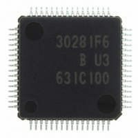
M30281F6HP#U3B Renesas Electronics America, M30281F6HP#U3B Datasheet - Page 385

M30281F6HP#U3B
Manufacturer Part Number
M30281F6HP#U3B
Description
IC M16C/28 MCU FLASH 48K 64LQFP
Manufacturer
Renesas Electronics America
Series
M16C™ M16C/Tiny/28r
Datasheet
1.M30280F6HPU9.pdf
(425 pages)
Specifications of M30281F6HP#U3B
Core Processor
M16C/60
Core Size
16-Bit
Speed
20MHz
Connectivity
I²C, IEBus, SIO, UART/USART
Peripherals
DMA, POR, PWM, Voltage Detect, WDT
Number Of I /o
55
Program Memory Size
48KB (48K x 8)
Program Memory Type
FLASH
Ram Size
4K x 8
Voltage - Supply (vcc/vdd)
2.7 V ~ 5.5 V
Data Converters
A/D 13x10b
Oscillator Type
Internal
Operating Temperature
-40°C ~ 85°C
Package / Case
64-LQFP
For Use With
R0K330290S000BE - KIT EVAL STARTER FOR M16C/29M30290T2-CPE - EMULATOR COMPACT M16C/26A/28/29M30290T2-CPE-HP - EMULATOR COMPACT FOR M16C/TINY
Lead Free Status / RoHS Status
Lead free / RoHS Compliant
Eeprom Size
-
Available stocks
Company
Part Number
Manufacturer
Quantity
Price
Part Number:
M30281F6HP#U3BM30281F6HP#D5
Manufacturer:
Renesas Electronics America
Quantity:
10 000
Part Number:
M30281F6HP#U3BM30281F6HP#U3
Manufacturer:
Renesas Electronics America
Quantity:
10 000
- Current page: 385 of 425
- Download datasheet (4Mb)
M
R
R
e
E
1
. v
J
6
0
20.6.2 Timer B
C
2
9
2 /
0 .
B
20.6.2.1 Timer B (Timer Mode)
20.6.2.2 Timer B (Event Counter Mode)
20.6.2.3 Timer B (Pulse Period/pulse Width Measurement Mode)
0
0
8
0
1. The timer remains idle after reset. Set the mode, count source, counter value, etc. using the TBiMR
2. The counter value can be read out at any time by reading the TBi register. However, if this register
1. The timer remains idle after reset. Set the mode, count source, counter value, etc. using the TBiMR
2. The counter value can be read out at any time by reading the TBi register. However, if this register
1. The timer remains idle after reset. Set the mode, count source, etc. using the TBiMR (i = 0 to 2)
2. The IR bit in TBiIC register (i=0 to 2) goes to “1” (interrupt request), when an effective edge of a
3. If the source of interrupt cannot be identified by the MR3 bit such as when the measurement pulse
4. To set the MR3 bit to “0” (no overflow), set TBiMR register with setting the TBiS bit to “1” and
5. Use the IR bit in TBiIC register to detect only overflows. Use the MR3 bit only to determine the
G
4
J
7
a
o r
(i = 0 to 2) register and TBi register before setting the TBiS bit in the TABSR register to “1” (count
starts).
Always make sure the TBiMR register is modified while the TBiS bit remains “0” (count stops)
regardless whether after reset or not.
is read at the same time the counter is reloaded, the read value is always “FFFF
register is read after setting a value in it but before the counter starts counting, the read value is the
one that has been set in the register.
register before setting the TBiS bit in the TABSR register to “1” (count starts).
Always make sure the TBiMR register is modified while the TBiS bit remains “0” (count stops)
regardless whether after reset or not. To clear the MR3 bit to “0” by writing to the TBiMR register
while the TBiS bit is set to “1” (count starts), be sure to write the same value as previously written to
the TM0D0, TM0D1, MR0, MR1, TCK0 and TCK1 bits and a 0 to the MR2 bit.
measurement pulse is input or timer Bi is overflowed. The factor of interrupt request can be deter-
mined by use of the MR3 bit in TBiMR register within the interrupt routine.
input and a timer overflow occur at the same time, use another timer to count the number of times
timer B has overflowed.
counting the next count source after setting the MR3 bit to “1” (overflow).
interrupt factor within the interrupt routine.
0 -
. n
u
2
3
p
0
, 1
0
(
M
2
0
1
0
6
7
C
2 /
page 363
, 8
M
1
6
C
2 /
f o
8
3
) B
8
5
16
16
20. Precautions
.” If the TBi
.” If the TBi
Related parts for M30281F6HP#U3B
Image
Part Number
Description
Manufacturer
Datasheet
Request
R

Part Number:
Description:
KIT STARTER FOR M16C/29
Manufacturer:
Renesas Electronics America
Datasheet:

Part Number:
Description:
KIT STARTER FOR R8C/2D
Manufacturer:
Renesas Electronics America
Datasheet:

Part Number:
Description:
R0K33062P STARTER KIT
Manufacturer:
Renesas Electronics America
Datasheet:

Part Number:
Description:
KIT STARTER FOR R8C/23 E8A
Manufacturer:
Renesas Electronics America
Datasheet:

Part Number:
Description:
KIT STARTER FOR R8C/25
Manufacturer:
Renesas Electronics America
Datasheet:

Part Number:
Description:
KIT STARTER H8S2456 SHARPE DSPLY
Manufacturer:
Renesas Electronics America
Datasheet:

Part Number:
Description:
KIT STARTER FOR R8C38C
Manufacturer:
Renesas Electronics America
Datasheet:

Part Number:
Description:
KIT STARTER FOR R8C35C
Manufacturer:
Renesas Electronics America
Datasheet:

Part Number:
Description:
KIT STARTER FOR R8CL3AC+LCD APPS
Manufacturer:
Renesas Electronics America
Datasheet:

Part Number:
Description:
KIT STARTER FOR RX610
Manufacturer:
Renesas Electronics America
Datasheet:

Part Number:
Description:
KIT STARTER FOR R32C/118
Manufacturer:
Renesas Electronics America
Datasheet:

Part Number:
Description:
KIT DEV RSK-R8C/26-29
Manufacturer:
Renesas Electronics America
Datasheet:

Part Number:
Description:
KIT STARTER FOR SH7124
Manufacturer:
Renesas Electronics America
Datasheet:

Part Number:
Description:
KIT STARTER FOR H8SX/1622
Manufacturer:
Renesas Electronics America
Datasheet:

Part Number:
Description:
KIT DEV FOR SH7203
Manufacturer:
Renesas Electronics America
Datasheet:


