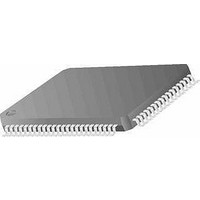
MC68HC11K0CFUE4 Freescale Semiconductor, MC68HC11K0CFUE4 Datasheet - Page 79

MC68HC11K0CFUE4
Manufacturer Part Number
MC68HC11K0CFUE4
Description
MCU 8-BIT 768 RAM 4MHZ 80-QFP
Manufacturer
Freescale Semiconductor
Series
HC11r
Specifications of MC68HC11K0CFUE4
Core Processor
HC11
Core Size
8-Bit
Speed
4MHz
Connectivity
SCI, SPI
Peripherals
POR, PWM, WDT
Number Of I /o
37
Program Memory Type
ROMless
Ram Size
768 x 8
Voltage - Supply (vcc/vdd)
4.5 V ~ 5.5 V
Data Converters
A/D 8x8b
Oscillator Type
Internal
Operating Temperature
-40°C ~ 85°C
Package / Case
80-QFP
Data Bus Width
8 bit
Data Ram Size
768 B
Interface Type
SCI, SPI
Maximum Clock Frequency
4 MHz
Number Of Programmable I/os
37
Number Of Timers
8
Maximum Operating Temperature
+ 85 C
Mounting Style
SMD/SMT
Minimum Operating Temperature
- 40 C
On-chip Adc
8 bit, 8 Channel
Lead Free Status / RoHS Status
Lead free / RoHS Compliant
Eeprom Size
-
Program Memory Size
-
Lead Free Status / Rohs Status
Details
Available stocks
Company
Part Number
Manufacturer
Quantity
Price
Company:
Part Number:
MC68HC11K0CFUE4
Manufacturer:
Freescale Semiconductor
Quantity:
10 000
- Current page: 79 of 290
- Download datasheet (4Mb)
4.5.4 Special Test Mode
4.5.5 Mode Selection
M68HC11K Family
MOTOROLA
For a detailed description of bootstrap mode, refer to the Motorola
application note entitled MC68HC11 Bootstrap Mode, document order
number AN1060/D.
Special test mode, a variation of the expanded mode, is used primarily
during Motorola’s internal production testing. However, for those devices
containing EPROM, it can be used to program the EPROM for program
calibration data in EEPROM and support emulation and debugging
during development.
For more detailed information, refer to
with Downloaded
The operating mode is selected by applying the appropriate logic states
to the MODA and MODB pins during reset. MODA selects single-chip
mode (0) or expanded mode (1). A logic high on MODB selects normal
modes, and vectors are fetched from memory area $FFC0–$FFFF. A
logic low on MODB selects special modes, and reset vectors are fetched
from memory area $BFC0–$BFFF. Values reflecting the selected mode
are latched into the RBOOT, SMOD, and MDA bits of the highest priority
I-bit interrupt and miscellaneous register (HPRIO) on the rising edge of
RESET.
Freescale Semiconductor, Inc.
Synchronization
For More Information On This Product,
Character
Operating Modes and On-Chip Memory
$FD
$FF
$FF
$F0
Table 4-2. Synchronization Character Selection
Go to: www.freescale.com
Data.
4.9 characters
13 characters
4 characters
4 characters
Timeout
Delay
4.7.1 Programming the EPROM
Operating Modes and On-Chip Memory
2 MHz
7812
1200
9600
3906
Baud Rate at E Clocks
11,718
14,400
3 MHz
1800
5859
Operating Modes
Technical Data
15,624
19,200
4 MHz
2400
7812
79
Related parts for MC68HC11K0CFUE4
Image
Part Number
Description
Manufacturer
Datasheet
Request
R

Part Number:
Description:
MC68HC11 EEPROM Programming from a Personal Computer
Manufacturer:
Motorola / Freescale Semiconductor
Part Number:
Description:
Manufacturer:
Freescale Semiconductor, Inc
Datasheet:
Part Number:
Description:
Manufacturer:
Freescale Semiconductor, Inc
Datasheet:
Part Number:
Description:
Manufacturer:
Freescale Semiconductor, Inc
Datasheet:
Part Number:
Description:
Manufacturer:
Freescale Semiconductor, Inc
Datasheet:
Part Number:
Description:
Manufacturer:
Freescale Semiconductor, Inc
Datasheet:
Part Number:
Description:
Manufacturer:
Freescale Semiconductor, Inc
Datasheet:
Part Number:
Description:
Manufacturer:
Freescale Semiconductor, Inc
Datasheet:
Part Number:
Description:
Manufacturer:
Freescale Semiconductor, Inc
Datasheet:
Part Number:
Description:
Manufacturer:
Freescale Semiconductor, Inc
Datasheet:
Part Number:
Description:
Manufacturer:
Freescale Semiconductor, Inc
Datasheet:
Part Number:
Description:
Manufacturer:
Freescale Semiconductor, Inc
Datasheet:
Part Number:
Description:
Manufacturer:
Freescale Semiconductor, Inc
Datasheet:
Part Number:
Description:
Manufacturer:
Freescale Semiconductor, Inc
Datasheet:
Part Number:
Description:
Manufacturer:
Freescale Semiconductor, Inc
Datasheet:


