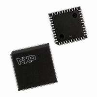
P87C51RC+4N,112 NXP Semiconductors, P87C51RC+4N,112 Datasheet - Page 20

P87C51RC+4N,112
Manufacturer Part Number
P87C51RC+4N,112
Description
IC 80C51 MCU 512 RAM 44-DIP
Manufacturer
NXP Semiconductors
Series
87Cr
Specifications of P87C51RC+4N,112
Core Processor
8051
Core Size
8-Bit
Speed
16MHz
Connectivity
EBI/EMI, UART/USART
Peripherals
POR, PWM, WDT
Number Of I /o
32
Program Memory Size
32KB (32K x 8)
Program Memory Type
OTP
Ram Size
512 x 8
Voltage - Supply (vcc/vdd)
2.7 V ~ 5.5 V
Oscillator Type
Internal
Operating Temperature
0°C ~ 70°C
Package / Case
40-DIP (0.600", 15.24mm)
For Use With
OM10064 - EMULATOR 80C51 PDS51-MK2
Lead Free Status / RoHS Status
Lead free / RoHS Compliant
Eeprom Size
-
Data Converters
-
Other names
935253430112
P87C51RC+4N
P87C51RC+4N
P87C51RC+4N
P87C51RC+4N
When Timer 2 is in the baud rate generator mode, one should not try
1. Capture/reload occurs only on timer/counter overflow.
2. Capture/reload occurs on timer/counter overflow and a 1-to-0 transition on T2EX (P1.1) pin except when Timer 2 is used in the baud rate
Philips Semiconductors
to read or write TH2 and TL2. As a baud rate generator, Timer 2 is
incremented every state time (osc/2) or asynchronously from pin T2;
under these conditions, a read or write of TH2 or TL2 may not be
accurate. The RCAP2 registers may be read, but should not be
written to, because a write might overlap a reload and cause write
and/or reload errors. The timer should be turned off (clear TR2)
before accessing the Timer 2 or RCAP2 registers.
Table 4 shows commonly used baud rates and how they can be
obtained from Timer 2.
Summary of Baud Rate Equations
Timer 2 is in baud rate generating mode. If Timer 2 is being clocked
through pin T2 (P1.0) the baud rate is:
Table 5.
Table 6.
NOTES:
2003 Jan 24
80C51 8-bit microcontroller family
with 512B/1KB RAM, low voltage (2.7 to 5.5 V), low power, high
speed (30/33 MHz)
16-bit Auto-Reload
16-bit Capture
Baud rate generator receive and transmit same baud rate
Receive only
Transmit only
16-bit
Auto-Reload
generator mode.
Baud Rate + Timer 2 Overflow Rate
Timer 2 as a Timer
Timer 2 as a Counter
16
MODE
MODE
8KB/16KB/32KB/64KB OTP
20
Except for the baud rate generator mode, the values given for T2CON
If Timer 2 is being clocked internally, the baud rate is:
Where f
To obtain the reload value for RCAP2H and RCAP2L, the above
equation can be rewritten as:
Timer/Counter 2 Set-up
do not include the setting of the TR2 bit. Therefore, bit TR2 must be
set, separately, to turn the timer on. see Table 5 for set-up of Timer 2
as a timer. Also see Table 6 for set-up of Timer 2 as a counter.
INTERNAL CONTROL
INTERNAL CONTROL
Baud Rate +
RCAP2H, RCAP2L + 65536 *
(Note 1)
(Note 1)
OSC
00H
01H
34H
24H
14H
02H
03H
= Oscillator Frequency
P87C51RA2/RB2/RC2/RD2
[ n *
* n =
[65536 * (RCAP2H, RCAP2L)]]
T2CON
TMOD
16 in 6-clock mode
32 in 12-clock mode
f
OSC
EXTERNAL CONTROL
EXTERNAL CONTROL
n *
Baud Rate
f
OSC
(Note 2)
(Note 2)
0AH
0BH
08H
09H
36H
26H
16H
Product data


