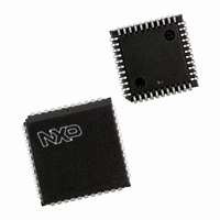
P87C51RC+4N,112 NXP Semiconductors, P87C51RC+4N,112 Datasheet - Page 52

P87C51RC+4N,112
Manufacturer Part Number
P87C51RC+4N,112
Description
IC 80C51 MCU 512 RAM 44-DIP
Manufacturer
NXP Semiconductors
Series
87Cr
Specifications of P87C51RC+4N,112
Core Processor
8051
Core Size
8-Bit
Speed
16MHz
Connectivity
EBI/EMI, UART/USART
Peripherals
POR, PWM, WDT
Number Of I /o
32
Program Memory Size
32KB (32K x 8)
Program Memory Type
OTP
Ram Size
512 x 8
Voltage - Supply (vcc/vdd)
2.7 V ~ 5.5 V
Oscillator Type
Internal
Operating Temperature
0°C ~ 70°C
Package / Case
40-DIP (0.600", 15.24mm)
For Use With
OM10064 - EMULATOR 80C51 PDS51-MK2
Lead Free Status / RoHS Status
Lead free / RoHS Compliant
Eeprom Size
-
Data Converters
-
Other names
935253430112
P87C51RC+4N
P87C51RC+4N
P87C51RC+4N
P87C51RC+4N
Philips Semiconductors
2003 Jan 24
AC inputs during testing are driven at V
NOTE:
Timing measurements are made at V
80C51 8-bit microcontroller family
with 512B/1KB RAM, low voltage (2.7 to 5.5 V), low power, high
speed (30/33 MHz)
V
CC
0.45V
–0.5
Figure 39. AC Testing Input/Output
15
10
40
35
30
25
20
5
0.2V
0.2V
IH
CC
CC
CC
Valid only within frequency specifications of the specified operating voltage
min for a logic ‘1’ and V
+0.9
–0.1
–0.5 for a logic ‘1’ and 0.45V for a logic ‘0’.
4
8
8KB/16KB/32KB/64KB OTP
Figure 41. I
IL
12
max for a logic ‘0’.
FREQ AT XTAL1 (MHz)
16
SU00717
CC
vs. FREQ for 12-clock operation
20
52
24
NOTE:
For timing purposes, a port is no longer floating when a 100mV change from
load voltage occurs, and begins to float when a 100mV change from the loaded
V
V
OH
LOAD
/V
OL
28
level occurs. I
V
V
LOAD
LOAD
32
P87C51RA2/RB2/RC2/RD2
–0.1V
+0.1V
OH
Figure 40. Float Waveform
/I
OL
36
MAX ACTIVE MODE
I
TYP ACTIVE MODE
MAX IDLE MODE
I
TYP IDLE MODE
CC
CC
MAX = 1.1
MAX = 0.22
20mA.
REFERENCE
TIMING
FREQ. + 1.0
POINTS
FREQ. + 1.0
SU01684
Product data
V
V
OH
OL
SU00718
+0.1V
–0.1V


