PTGL09AR390N0B52A0 Murata Electronics North America, PTGL09AR390N0B52A0 Datasheet - Page 78
PTGL09AR390N0B52A0
Manufacturer Part Number
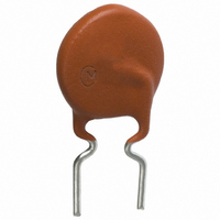
PTGL09AR390N0B52A0
Description
THERM 39 OHM 250V PTC RADIAL
Manufacturer
Murata Electronics North America
Series
PTGLr
Datasheet
1.PTGL09AR390N0B52A0.pdf
(95 pages)
Specifications of PTGL09AR390N0B52A0
Voltage - Max
250V
Current - Hold (ih) (max)
115mA
Current - Trip (it)
245mA
Current - Max
600mA
Package / Case
Radial
Lead Free Status / RoHS Status
Lead free by exemption / RoHS compliant by exemption
R Min/max
-
Time To Trip
-
Other names
490-4809-3


11
!Note
• This PDF catalog is downloaded from the website of Murata Manufacturing co., ltd. Therefore, it’s specifications are subject to change or our products in it may be discontinued without advance notice. Please check with our
• This PDF catalog has only typical specifications because there is no space for detailed specifications. Therefore, please approve our product specifications or transact the approval sheet for product specifications before ordering.
sales representatives or product engineers before ordering.
!Note
76
No.
*: The resistance measurement after the test.
**: Above mentioned soldering is done following condition at our side.
For Overheat Sensing Chip Tight Tolerance Type Specifications and Test Methods
1
2
3
4
5
6
7
8
9
PRF15_RB6RC Series
It is measured by applying voltage less than 3VDC after left at 25 2 C for 2 hours.
· Glass-Epoxy PC board
· Standard land dimension
· Standard solder paste
· Standard solder profile
Above conditions are mentioned in Notice.
Resistance Value (at 25 C)
Vibration
Solderability
Solder-heatability
Dry heat resistance
Cold resistance
Humidity Test
Temperature Cycling
High Temperature Load Test
• Please read rating and !CAUTION (for storage, operating, rating, soldering, mounting and handling) in this catalog to prevent smoking and/or burning, etc.
• This catalog has only typical specifications because there is no space for detailed specifications. Therefore, please approve our product specifications or transact the approval sheet for product specifications before ordering.
Item
The resistance value should be within the
specified tolerance.
There is No abnormal appearance after the test.
Resistance change is less than 20%.(*)
Min. 95% electrode is covered with new solder.
Resistance change is less than 20%.(*)
There is No abnormal appearance after the test.
Resistance change is less than 20%.(*)
There is No abnormal appearance after the test.
Resistance change is less than 20%.(*)
Rating value
After applying maximum operating voltage for 3 minutes and
leaving for 2 hours at 25 C, measured by applying voltage of
less than 3VDC.
Soldered PTC to PCB (**)
· Vibration: 10 to 55 to 10Hz (1min.)
· Max. Amplitude: 1.5mm
Vibrate for 2 hours in each of 3 mutually perpendicular plane for
a total of 12hours.
This test condition is according to "JIS C 60068-2-6 (1999)".
· Solder temp.: 230 5 C
· Solder: Sn 63%/Pb 37% (or 60/40%)
· Soaking time: 3 0.5 secs.
· Soaking position: Until a whole electrode is soaked.
This test condition is according to "JIS C 60068-2-58 (2006)".
· Solder temp.: 260 5 C
· Solder: Sn 63%/Pb 37% (or 60/40%)
· Flax: Containing less than 0.2wt% of chlorine.
· Soaking time: 10 1 secs.
· Soaking position: Until a whole electrode is soaked.
· Preheating: 150 5 C 3 mins.
This test condition is according to "JIS C 60068-2-58 (2006)".
· Soldered PTC to PCB. (**)
· +125 3 C leave for 1000+12/-0 hrs.
This test condition is according to "JIS C 60068-2-2 (1995)"
· Soldered PTC to PCB. (**)
· -20 3 C leave for 1000+12/-0 hrs.
· Soldered PTC to PCB. (**)
· +60 3 C, 90 to 95%RH leave for 1000+12/-0 hrs.
· Soldered PTC to PCB. (**)
· Cycles: 5 cycles
· Conditions: See below table
· Soldered PTC to PCB. (**)
· 85 3 C (in air), load max. operating voltage for 1000 12 hrs.
Step
1
2
3
4
Room temp.
Room temp.
Temp. ( C)
+125+3, -0
-20+0, -3
Method of Examination
Time (minute)
10 to 15
10 to 15
30
30
R90E.pdf
10.3.4
Related parts for PTGL09AR390N0B52A0
Image
Part Number
Description
Manufacturer
Datasheet
Request
R

Part Number:
Description:
BUZZER PIEZO 25VP-P SMD
Manufacturer:
Murata Electronics North America

Part Number:
Description:
CAP 4-ARRAY 680PF 100V X7R 1206
Manufacturer:
Murata Electronics North America
Datasheet:
Part Number:
Description:
CAP 4-ARRAY 1000PF 100V X7R 1206
Manufacturer:
Murata Electronics North America
Datasheet:
Part Number:
Description:
CAP 4-ARRAY 1800PF 100V X7R 1206
Manufacturer:
Murata Electronics North America
Datasheet:
Part Number:
Description:
CAP 4-ARRAY 68000PF 16V X7R 1206
Manufacturer:
Murata Electronics North America
Datasheet:

Part Number:
Description:
CAP CER 1000PF 50V 10% X7R 0402
Manufacturer:
Murata Electronics North America
Datasheet:
Part Number:
Description:
CAP CER 10000PF 16V 10% X7R 0402
Manufacturer:
Murata Electronics North America
Datasheet:

Part Number:
Description:
CAP 5.5-25PF 2.5X3.2MM SMD
Manufacturer:
Murata Electronics North America
Datasheet:

Part Number:
Description:
CAP 4.5-20PF 2.5X3.2MM SMD
Manufacturer:
Murata Electronics North America
Datasheet:

Part Number:
Description:
CAP 5.0-20PF 3.2X4.5MM SMD RED
Manufacturer:
Murata Electronics North America
Datasheet:

Part Number:
Description:
CAP 2.0-6.0PF 3.2X4.5MM SMD BLU
Manufacturer:
Murata Electronics North America
Datasheet:

Part Number:
Description:
CAP 1.4-3.0PF 3.2X4.5MM SMD BRN
Manufacturer:
Murata Electronics North America
Datasheet:

Part Number:
Description:
CAP 3.0-10PF 3.2X4.5MM SMD WHT
Manufacturer:
Murata Electronics North America
Datasheet:

Part Number:
Description:
CAP 2.0-6.0PF 4X4.5MM TOPADJ BLU
Manufacturer:
Murata Electronics North America
Datasheet:

Part Number:
Description:
CAP 8.5-40PF 4X4.5MM TOPADJ YEL
Manufacturer:
Murata Electronics North America
Datasheet: