ATAB5570 Atmel, ATAB5570 Datasheet - Page 5
ATAB5570
Manufacturer Part Number
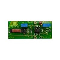
ATAB5570
Description
BOARD EVAL FOR ATAB5570
Manufacturer
Atmel
Type
Development kitr
Specifications of ATAB5570
Contents
Fully Assembled Evaluation Board
Product
RFID Transponders
For Use With/related Products
ATA5570
Lead Free Status / RoHS Status
Contains lead / RoHS non-compliant


Figure 4-2.
4.10
4863A–RFID–07/05
Modulator
L
0
1
1) If Master Key = 6 and bit 15 set, then test-mode access is disabled and extended mode is active
2) If Master Key = 9 and bit 15 set, then extended mode is enabled
Master Key
1
Unlocked
Locked
Note 1), 2)
1
Block 0 Configuration Mapping – e5550 Compatibility Mode
0
2
3 4
0
1
0
5
The modulator consists of data encoders for the following basic types of modulation:
Table 4-1.
Mode
Direct Data Output
FSK1a
FSK2a
FSK1
FSK2
PSK1
PSK2
PSK3
Manchester
Bi-phase
NRZ
Notes:
0
6
0
7 8
(1)
(1)
(2)
(2)
(2)
(1)
(1)
0
1. A common multiple of bit rate and FSK frequencies is recommended.
2. In PSK mode the selected data rate has to be an integer multiple of the PSK sub-carrier
n5 n4 n3 n2 n1 n0
9 10 11 12
frequency.
Data Bit Rate
Types of e5550-compatible Modulation Modes
RF/(2n + 2)
Direct
PSK1
PSK2
PSK3
FSK1
FSK2
Mode-Defeat 1
Mode-Defeat 2
Manchester
Biphase ('50)
Biphase ('57)
13 14 15 16 17 18 19 20
1
0
0
0
0
0
0
0
0
0
1
1
Modulation
Encoding
FSK/8, FSK/5
FSK/8, FSK/10
FSK/5, FSK/8
FSK/10, FSK/8
Phase change when input changes
Phase change on bit clock if input high
Phase change on rising edge of input
“0” = falling edge, “1” = rising edge
“1” creates an additional mid-bit change
“1” = damping on, “0” = damping off
0
0
0
0
0
0
0
0
1
0
1
0
0
0
0
1
1
1
1
0
0
0
0
0
1
1
0
0
1
1
0
0
0
0
1
0
1
0
1
0
1
0
0
0
21 22 23 24 25 26 27 28 29 30 31 32
PSK-
0
0
1
1
CF
ATA5570 [Preliminary]
0
1
0
1
RF/2
RF/4
RF/8
Res.
“0” = RF/8;
“0” = RF/8;
“0” = RF/5;
“0” = RF/10;
BLOCK
MAX-
“1” = RF/5
“1” = RF/10
“1” = RF/8
“1” = RF/8
5
Related parts for ATAB5570
Image
Part Number
Description
Manufacturer
Datasheet
Request
R

Part Number:
Description:
DEV KIT FOR AVR/AVR32
Manufacturer:
Atmel
Datasheet:

Part Number:
Description:
INTERVAL AND WIPE/WASH WIPER CONTROL IC WITH DELAY
Manufacturer:
ATMEL Corporation
Datasheet:
Part Number:
Description:
Low-Voltage Voice-Switched IC for Hands-Free Operation
Manufacturer:
ATMEL Corporation
Datasheet:
Part Number:
Description:
MONOLITHIC INTEGRATED FEATUREPHONE CIRCUIT
Manufacturer:
ATMEL Corporation
Datasheet:
Part Number:
Description:
AM-FM Receiver IC U4255BM-M
Manufacturer:
ATMEL Corporation
Datasheet:
Part Number:
Description:
Monolithic Integrated Feature Phone Circuit
Manufacturer:
ATMEL Corporation
Datasheet:
Part Number:
Description:
Multistandard Video-IF and Quasi Parallel Sound Processing
Manufacturer:
ATMEL Corporation
Datasheet:
Part Number:
Description:
High-performance EE PLD
Manufacturer:
ATMEL Corporation
Datasheet:
Part Number:
Description:
8-bit Flash Microcontroller
Manufacturer:
ATMEL Corporation
Datasheet:
Part Number:
Description:
2-Wire Serial EEPROM
Manufacturer:
ATMEL Corporation
Datasheet: