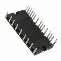
STGIPL14K60 STMicroelectronics, STGIPL14K60 Datasheet - Page 17

STGIPL14K60
Manufacturer Part Number
STGIPL14K60
Description
IGBT IPM MODULE 14A 600V 38SDIP
Manufacturer
STMicroelectronics
Type
IGBTr
Specifications of STGIPL14K60
Configuration
3 Phase
Current
14A
Voltage
600V
Voltage - Isolation
2500VDC
Package / Case
38-SDIP Module
Module Configuration
3-Phase Bridge
Transistor Polarity
N Channel
Dc Collector Current
15A
Collector Emitter Voltage Vces
600V
Power Dissipation Pd
44W
Operating Temperature Range
-40°C To
Rohs Compliant
Yes
Collector- Emitter Voltage Vceo Max
600 V
Collector-emitter Saturation Voltage
1.8 V
Continuous Collector Current At 25 C
14 A
Power Dissipation
35 W
Maximum Operating Temperature
+ 125 C
Minimum Operating Temperature
- 40 C
Mounting Style
Through Hole
Operating Temperature (max)
125C
Operating Temperature (min)
-40C
Pin Count
38
Mounting
Through Hole
Screening Level
Automotive
Lead Free Status / RoHS Status
Lead free / RoHS Compliant
Other names
497-10571-5
Available stocks
Company
Part Number
Manufacturer
Quantity
Price
Company:
Part Number:
STGIPL14K60
Manufacturer:
STMicroelectronics
Quantity:
120
STGIPL14K60
5.1
Recommendations
●
●
●
●
●
●
●
●
Table 15.
Symbol
f
t
V
V
V
PWM
dead
CC
PN
BS
Input signal HIN is active high logic. A 85kΩ (typ.) pull down resistor is built-in for each
high side input. If an external RC filter is used, for noise immunity, pay attention to the
variation of the input signal level.
Input signal LIN is active low logic. A 720 kΩ (typ.) pull-up resistor, connected to an
internal 5 V regulator through a diode, is built-in for each low side input.
To prevent the input signals oscillation, the wiring of each input should be as short as
possible.
By integrating an application specific type HVIC inside the module, direct coupling to
MCU terminals without any opto-coupler is possible.
Each capacitor should be located as nearby the pins of IPM as possible.
Low inductance shunt resistors should be used for phase leg current sensing.
Electrolytic bus capacitors should be mounted as close to the module bus terminals as
possible. Additional high frequency ceramic capacitor mounted close to the module
pins will further improve performance.
The SD/OD signal should be pulled up to 5 V / 3.3 V with an external resistor (see
Section 4: Smart shutdown function
Control supply voltage Applied between V
High side bias voltage
prevent Arm-short
PWM input signal
Recommended operating conditions
Blanking time to
Supply Voltage
Parameter
Doc ID 15589 Rev 5
Applied between P-Nu, Nv, Nw
Applied between V
i = U, V, W
For each input signal
-40°C < T
-40°C < T
for detailed info).
c
j
< 125°C
< 100°C
Conditions
CC
BOOTi
-GND
-OUT
i
for
Applications information
Min.
13.5
13
1
Value
Typ.
300
15
Max.
400
18
18
20
Unit
17/22
kHz
µs
V
V
V


