SCP1000 PCB1 VTI Technologies, SCP1000 PCB1 Datasheet - Page 16
SCP1000 PCB1
Manufacturer Part Number
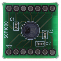
SCP1000 PCB1
Description
SENSOR SPI 30-120KPA PCB
Manufacturer
VTI Technologies
Series
SCP1000r
Datasheet
1.SCP1000_PCB3.pdf
(37 pages)
Specifications of SCP1000 PCB1
Pressure Type
Absolute
Operating Pressure
4.35 ~ 17.40 PSI, 30 ~ 120 kPa
Output
Digital
Voltage - Supply
2.4 V ~ 3.3 V
Termination Style
Surface Mount
Operating Temperature
-20°C ~ 70°C
Package / Case
PCB Mount
Lead Free Status / RoHS Status
Lead free / RoHS Compliant
Other names
551-1042


2.3 Over Pressure
2.4 DRDY – data ready pin
2.5 TRIG – trigger pin
2.6 Power Down Mode and PD Pin
2.7 Standby Mode
2.8 Reset
2.9 Clock
VTI Technologies Oy
www.vti.fi
When operating within the nominal operation range (30…120 kPa) the output of the SCP1000
changes between 120000 and 480000. In major over pressure situations (over 131 kPa), a sudden
drop of the output reading can be observed, since the SCP1000 pressure output is not limited.
Availability of updated pressure and temperature data is signaled through the assertion of the
DRDY pin. DRDY is cleared after the DATARD16 register is read, see section 2.2.1 for more
detailed information.
TRIG pin is used to trig the measurement in low power measurement mode (external trigger). The
µC has to actively drive the signal in high and low states. In applications where the TRIG signal is
not used it has be connected to DVSS. See section 2.2.4.4 for more detailed information.
In order to decrease further the current consumption in cases where there are long time intervals
between the measurements, SCP1000 has a built in power down mode, which can be activated
through the PD pin. SCP1000 will stay in power down mode as long as the PD signal is high. In
power down mode every digital output pin of SCP1000 tristates.
After PD signal changes back to low, SCP1000 powers up, performs initialization and is ready to
operate. Start-up sequence has to be executed always after power down mode, see section 2.1 for
more detailed information.
The advantage of using power down mode instead of switching off the supply is that during wake-
up from power down there is no need to recharge the filter capacitors on AVDD and DVDD lines.
The µC has to actively drive the signal in high and low states. In applications where the PD signal
is not used it has to be connected to DVSS.
The current consumption of SCP1000 in power down mode is typically 0.2 µA.
SCP1000 is in standby mode after start-up, when OPERATION register content is 0x00 and in ultra
low power measurement mode between the measurements. The average current consumption is in
the range of 1 µA.
SCP1000 ASIC software can be reseted by writing 0x01 in to RSTR register. After reset the RSTR
register content is set to 0x00 and the default values are loaded from EEPROM. The start-up
sequence should be followed from section 2.1.2 onwards after reset.
The SCP1000 pressure sensor is operated with internal clock, so external clock signal is not
needed.
Doc.Nr. 8260800.08
Subject to changes
SCP1000 Series
Rev.0.08
16/37
Related parts for SCP1000 PCB1
Image
Part Number
Description
Manufacturer
Datasheet
Request
R


Part Number:
Description:
SENSOR 30-120KPA SPI
Manufacturer:
VTI Technologies
Datasheet:

Part Number:
Description:
SENSOR I2C 30-120KPA PCB
Manufacturer:
VTI Technologies
Datasheet:

Part Number:
Description:
SENSOR I2C 30-120KPA
Manufacturer:
VTI Technologies
Datasheet:

Part Number:
Description:
ACCELEROMETER SGL 1.7G DIL8 SMD
Manufacturer:
VTI Technologies
Datasheet:

Part Number:
Description:
VTI Automotive Digital Accelerometer Platform
Manufacturer:
VTI [VTI technologies]
Datasheet:

Part Number:
Description:
BOARD PWB ACCEL 3-AXIS SPI/I2C
Manufacturer:
VTI Technologies
Datasheet:

Part Number:
Description:
EVAL BOARD ACCELEROMETER Y-AXIS
Manufacturer:
VTI Technologies
Datasheet:

Part Number:
Description:
EVAL BOARD INCLINOMETER Y-AXIS
Manufacturer:
VTI Technologies
Datasheet:

Part Number:
Description:
KIT DEMO ACCELEROMTR CMA3000-D01
Manufacturer:
VTI Technologies
Datasheet:
Part Number:
Description:
ACCELEROMETER SGL 1.7G DIL8 SMD
Manufacturer:
VTI Technologies
Datasheet:
Part Number:
Description:
VTI Automotive Digital Accelerometer Platform
Manufacturer:
VTI [VTI technologies]
Datasheet:
Part Number:
Description:
Accelerometer
Manufacturer:
VTI [VTI technologies]
Datasheet:
Part Number:
Description:
Stand Alone Inclinometer
Manufacturer:
VTI [VTI technologies]
Datasheet:
Part Number:
Description:
3-axis accelerometer
Manufacturer:
VTI [VTI technologies]
Datasheet: