SCP1000 PCB1 VTI Technologies, SCP1000 PCB1 Datasheet - Page 8
SCP1000 PCB1
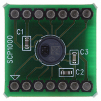
Manufacturer Part Number
SCP1000 PCB1
Description
SENSOR SPI 30-120KPA PCB
Manufacturer
VTI Technologies
Series
SCP1000r
Datasheet
1.SCP1000_PCB3.pdf
(37 pages)
Specifications of SCP1000 PCB1
Pressure Type
Absolute
Operating Pressure
4.35 ~ 17.40 PSI, 30 ~ 120 kPa
Output
Digital
Voltage - Supply
2.4 V ~ 3.3 V
Termination Style
Surface Mount
Operating Temperature
-20°C ~ 70°C
Package / Case
PCB Mount
Lead Free Status / RoHS Status
Lead free / RoHS Compliant
Other names
551-1042


2.1.1
2.1.2
2.1.2.1
VTI Technologies Oy
www.vti.fi
Power down-pin (PD) during start-up (Phase 1)
SCP1000 initialization during start-up (Phase 2)
SCP1000 initialization status check (optional)
Figure 3. Routine for start-up status check (optional).
SCP1000 has an external power down (PD) pin. In case the system has power management
capabilities, it is recommended that during power up the PD pin is tied to DVDD – this way the
sensor is forced to remain in power down mode during the stabilization of the power supplies. After
approximately 1ms (or longer depending on the power supply stabilization time) the PD pin can be
switched to DVSS allowing the sensor to start the power up and the initialization procedure to
begin.
In case the system does not have power management capability the PD pin can be tied to DVSS.
A 60 ms delay after the start-up (Phase 1 in Figure 2) is recommended. After the delay initialization
will be finished and all configuration registers are loaded with their default values. During the 60 ms
start-up delay there should not be any interface activity attempts.
Start-up status check is optional and can be replaced with 90 ms delay, see Figure 2.
The start-up status check includes EEPROM checksum error result check. The routine is described
in Figure 3 and in sections 2.1.2.1 and 2.1.2.2 below.
The STATUS register 0x07 (see Figure 3) can be read to verify that start-up procedure is finished.
If the STARTUP bit (LSB) of the STATUS register (0X07) is ‘0’, the start-up procedure is finished
successfully. If the STARTUP bit of the STATUS register is ‘1’, the start-up procedure is still
running.
If the start-up procedure is still running, it is advised to re-check the STATUS register after a delay.
A recommend delay is 10ms. If the start-up procedure is not finished after the additional delay, the
re-check procedure can be started again (see Figure 3). In order to avoid infinite loop in case of
sensor malfunction it is advisable to limit the maximum number of cycles. Recommended value is 6
cycles when using 10 ms additional delay. If the start-up procedure is not finished successfully after
the maximum number of STATUS register re-check cycles has expired, the start-up procedure has
failed.
STATUS register
standby mode
SCP1000 is in
measurement
waiting for
YES
YES
DATARD8
register
command
LSB = 0
LSB = 1
0x07
READ
READ
N1)
N4)
NO
NO
checksum error
ERROR EXIT
ERROR EXIT
loop counter
Loop count
start-up fail
≥ MAX
EEPROM
Increment
YES
N2)
Doc.Nr. 8260800.08
Subject to changes
NO
Delay 10 ms
N3)
N1)
N2
N3
N4
)
)
)
See
me
The maximum number of retries (MAX loop count)
depends entirel
rec
The
dep
def
DA
inte
interface (SCP10
0x0
ans that start-up procedure is finished.
ommended value is 6.
ault value is 10 ms.
TARD8 register has address 0x1F when
ending on the system desig
rface (SCP1000-D01) and 0x7F when u
1, the EEPROM checksum is correct.
recommended loop delay time can be chang
the status register details in section 3.2. LSB = ‘0’
y on the system design. The
00-D11). If the content of DATARD8 is
n. The recommended
SCP1000 Series
sing TWI
using SPI
Rev.0.08
ed
8/37
Related parts for SCP1000 PCB1
Image
Part Number
Description
Manufacturer
Datasheet
Request
R


Part Number:
Description:
SENSOR 30-120KPA SPI
Manufacturer:
VTI Technologies
Datasheet:

Part Number:
Description:
SENSOR I2C 30-120KPA PCB
Manufacturer:
VTI Technologies
Datasheet:

Part Number:
Description:
SENSOR I2C 30-120KPA
Manufacturer:
VTI Technologies
Datasheet:

Part Number:
Description:
ACCELEROMETER SGL 1.7G DIL8 SMD
Manufacturer:
VTI Technologies
Datasheet:

Part Number:
Description:
VTI Automotive Digital Accelerometer Platform
Manufacturer:
VTI [VTI technologies]
Datasheet:

Part Number:
Description:
BOARD PWB ACCEL 3-AXIS SPI/I2C
Manufacturer:
VTI Technologies
Datasheet:

Part Number:
Description:
EVAL BOARD ACCELEROMETER Y-AXIS
Manufacturer:
VTI Technologies
Datasheet:

Part Number:
Description:
EVAL BOARD INCLINOMETER Y-AXIS
Manufacturer:
VTI Technologies
Datasheet:

Part Number:
Description:
KIT DEMO ACCELEROMTR CMA3000-D01
Manufacturer:
VTI Technologies
Datasheet:
Part Number:
Description:
ACCELEROMETER SGL 1.7G DIL8 SMD
Manufacturer:
VTI Technologies
Datasheet:
Part Number:
Description:
VTI Automotive Digital Accelerometer Platform
Manufacturer:
VTI [VTI technologies]
Datasheet:
Part Number:
Description:
Accelerometer
Manufacturer:
VTI [VTI technologies]
Datasheet:
Part Number:
Description:
Stand Alone Inclinometer
Manufacturer:
VTI [VTI technologies]
Datasheet:
Part Number:
Description:
3-axis accelerometer
Manufacturer:
VTI [VTI technologies]
Datasheet: