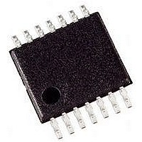
PIC16LF1824-I/ST Microchip Technology, PIC16LF1824-I/ST Datasheet - Page 29

PIC16LF1824-I/ST
Manufacturer Part Number
PIC16LF1824-I/ST
Description
IC PIC MCU 8BIT 14KB FSH 14TSSOP
Manufacturer
Microchip Technology
Series
PIC® XLP™ 16Fr
Specifications of PIC16LF1824-I/ST
Core Size
8-Bit
Program Memory Size
7KB (4K x 14)
Core Processor
PIC
Speed
32MHz
Connectivity
I²C, SPI, UART/USART
Peripherals
Brown-out Detect/Reset, POR, PWM, WDT
Number Of I /o
11
Program Memory Type
FLASH
Eeprom Size
256 x 8
Ram Size
256 x 8
Voltage - Supply (vcc/vdd)
1.8 V ~ 3.6 V
Data Converters
A/D 8x10b
Oscillator Type
Internal
Operating Temperature
-40°C ~ 85°C
Package / Case
14-TSSOP (0.173", 4.40mm Width)
Controller Family/series
PIC16LF
No. Of I/o's
12
Eeprom Memory Size
256Byte
Ram Memory Size
256Byte
Cpu Speed
32MHz
No. Of Timers
5
Lead Free Status / RoHS Status
Lead free / RoHS Compliant
Available stocks
Company
Part Number
Manufacturer
Quantity
Price
Company:
Part Number:
PIC16LF1824-I/ST
Manufacturer:
MICROCHIP
Quantity:
885
6.0
Code protection is controlled using the CP bit in
Configuration Word 1. When code protection is
enabled, all program memory locations (0000h-7FFFh)
read as all ‘0’. Further programming is disabled for the
program memory (0000h-7FFFh).
Data memory is protected with its own code-protect bit
(CPD). When data code-protection is enabled (CPD = 0),
all data memory locations read as ‘0’. Further
programming is disabled for the data memory. Data
memory can still be programmed and read during
program execution.
The user ID locations and Configuration Words can be
programmed and read out regardless of the code
protection settings.
6.1
Code protection is enabled by programming the CP bit
in Configuration Word 1 register to ‘0’.
The only way to disable code protection is to use the
Bulk Erase Program Memory command.
6.2
Data memory protection is enabled by programming
the CPD bit in Configuration Word 1 register to ‘0’.
The only way to disable code protection is to use the
Bulk Erase Program Memory command.
2010 Microchip Technology Inc.
Note:
CODE PROTECTION
Program Memory
Data Memory
To ensure system security, if CPD bit = 0,
the Bulk Erase Program Memory command
will also erase data memory.
PIC16F/LF182X/PIC12F/LF1822
Advance Information
7.0
In the hex file there are two bytes per program word
stored in the Intel
LSB first, MSB second. Because there are two bytes
per word, the addresses in the hex file are 2x the
address in program memory. (Example: Configuration
Word 1 is stored at 8007h on the PIC16F/LF182X and
PIC12F/LF1822. In the hex file this will be referenced
as 1000Eh-1000Fh).
7.1
To allow portability of code, it is strongly recommended
that the programmer is able to read the Configuration
Words and user ID locations from the hex file. If the
Configuration Words information was not present in the
hex file, a simple warning message may be issued.
Similarly, while saving a hex file, Configuration Words
and user ID information should be included.
7.2
If a device ID is present in the hex file at 1000Ch-
1000Dh (8006h on the part), the programmer should
verify the device ID (excluding the revision) against the
value read from the part. On a mismatch condition the
programmer should generate a warning message.
7.3
The programmer should be able to read data memory
information from a hex file and write data memory
contents to a hex file.
The physical address range of the 256 byte data
memory is 0000h-00FFh. However, these addresses
are logically mapped to address 1E000h-1E1FFh in the
hex file. This provides a way of differentiating between
the data and program memory locations in this range.
The format for data memory storage is one data byte
per address location, LSb aligned.
HEX FILE USAGE
Configuration Word
Device ID and Revision
Data EEPROM
®
INHX32 hex format. Data is stored
DS41390C-page 29


