TFDU6103-TR3 Vishay, TFDU6103-TR3 Datasheet - Page 3
TFDU6103-TR3
Manufacturer Part Number
TFDU6103-TR3
Description
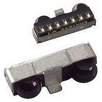
Infrared Transceivers SIR 115.2kbits Side View
Manufacturer
Vishay
Type
Fastr
Datasheet
1.TFDU6103-TR3.pdf
(13 pages)
Specifications of TFDU6103-TR3
Data Transmission Rate
4000 Kbits/s
Input Current
10 mA
Mounting Style
SMD/SMT
Power Dissipation
500 mW
Wavelength
886 nm
Continual Data Transmission
4 Mbit/s
Transmission Distance
1 m
Radiant Intensity
170 mW/sr
Half Intensity Angle Degrees
48 deg
Pulse Width
2.1 us
Maximum Rise Time
40 ns
Maximum Fall Time
40 ns
Led Supply Voltage
- 0.5 V to 6.5 V
Maximum Forward Current
10 mA
Operating Voltage
2.4 V to 5.5 V
Maximum Operating Temperature
+ 85 C
Minimum Operating Temperature
- 25 C
Dimensions
9.7 mm x 4.7 mm x 4 mm
Data Rate Max
4Mbps
Data Transmission Distance
1m
Peak Wavelength
886nm
Supply Current
2mA
Supply Voltage Range
2.4V To 5.5V
Operating Temperature Range
-25°C To +85°C
Msl
MSL 4 - 72 Hours
Data Rate
4Mbps
Angle Of Half Sensitivity
48°
Communication Distance
100
Package Type
Ultra Small Profile
Fall Time
40ns
Rise Time
40ns
Operating Supply Voltage (typ)
2.5/3.3/5V
Operating Supply Voltage (min)
2.4V
Operating Supply Voltage (max)
5.5V
Mounting
Surface Mount
Pin Count
8
Operating Temp Range
-25C to 85C
Operating Temperature Classification
Commercial
Idle Current, Typ @ 25° C
2mA
Link Range, Low Power
1m
Operating Temperature
-25°C ~ 85°C
Orientation
Side View
Shutdown
*
Size
9.7mm x 4.7mm x 4mm
Standards
IrPHY 1.4
Supply Voltage
2.4 V ~ 5.5 V
Lead Free Status / RoHS Status
Lead free / RoHS Compliant
Lead Free Status / RoHS Status
Lead free / RoHS Compliant, Lead free / RoHS Compliant
Available stocks
Company
Part Number
Manufacturer
Quantity
Price
Company:

Part Number:
TFDU6103-TR3
Manufacturer:
ST
Quantity:
1 001
Company:
Part Number:
TFDU6103-TR3
Manufacturer:
VISHAY
Quantity:
6 580


Note
Reference point ground pin 8, unless otherwise noted.
Typical values are for design aid only, not guaranteed nor subject to production testing and may vary with time.
Note
Vishay transceivers operating inside the absolute maximum ratings are classified as eye safe according the above table.
Document Number: 81211
Rev. 1.4, 29-Jul-09
ABSOLUTE MAXIMUM RATINGS
PARAMETER
Supply voltage range,
transceiver
Supply voltage range,
transmitter
Input currents
Output sinking current
Power dissipation
Junction temperature
Ambient temperature range
(operating)
Storage temperature range
Soldering temperature
Average output current
Repetitive pulse output current
IRED anode voltage
Voltage at all inputs and outputs
EYE SAFETY INFORMATION
STANDARD
IEC/EN 60825-1 (2007-03), DIN EN 60825-1 (2008-05) “SAFETY OF LASER PRODUCTS -
Part 1: equipment classification and requirements”, simplified method
IEC 62471 (2006), CIE S009 (2002) “Photobiological Safety of Lamps and Lamp Systems”
DIRECTIVE 2006/25/EC OF THE EUROPEAN PARLIAMENT AND OF THE COUNCIL of 5
on the minimum health and safety requirements regarding the exposure of workers to risks arising from
physical agents (artificial optical radiation) (19
of directive 89/391/EEC)
ELECTRICAL CHARACTERISTICS
PARAMETER
TRANSCEIVER
Supply voltage
Dynamic supply current
Shutdown supply current
Operating temperature range
Input voltage low
(TXD, SD)
Fast Infrared Transceiver Module (FIR, 4 Mbit/s)
irdasupportAM@vishay.com, irdasupportAP@vishay.com,
For technical questions within your region, please contact one of the following:
See recommended solder profile
sensitive, detector is disabled in
temperature range, not ambient
See derating curve, figure 6
T = 25 °C, not ambient light
SD = high, full specified
except IRED anode pin
for 2.4 V to 5.5 V Operation
V
TEST CONDITIONS
TEST CONDITIONS
< 90 µs, t
IN
0 V < V
0 V < V
shutdown mode
MIR/FIR mode
> V
light sensitive
(see figure 4)
For all pins,
th
SIR mode
SD = high
CC1
individual directive within the meaning of article 16(1)
CC2
CC1
on
is allowed
(1)
< 20 %
< 6 V
< 6 V
In transmit mode, add additional 85 mA (typ.) for IRED current.
Add RXD output current depending on RXD load.
I
I
SYMBOL
SYMBOL
IRED
IRED
V
Receive mode only, idle
V
V
T
V
T
IREDA
V
I
I
I
I
V
P
T
T
CC1
CC2
amb
CC
CC
SD
SD
stg
CC
IN
IL
D
A
J
(DC)
(RP)
irdasupportEU@vishay.com
th
April 2006
MIN.
- 0.5
- 0.5
- 0.5
MIN.
- 0.5
- 25
- 25
- 25
2.4
Vishay Semiconductors
TYP.
TYP.
0.01
1.8
2
CLASSIFICATION
Exempt
Class 1
Exempt
MAX.
MAX.
+ 6.5
+ 6.5
TFDU6103
+ 85
+ 85
+ 85
500
125
260
125
600
+ 6
5.5
5.5
3.3
0.5
10
25
3
1
www.vishay.com
UNIT
UNIT
mW
mA
mA
mA
mA
mA
mA
µA
µA
°C
°C
°C
°C
°C
V
V
V
V
V
V
3
Related parts for TFDU6103-TR3
Image
Part Number
Description
Manufacturer
Datasheet
Request
R

Part Number:
Description:
Manufacturer:
Vishay Semiconductors
Datasheet:

Part Number:
Description:
Infrared Transceivers SIR 115.2kbits Top View
Manufacturer:
Vishay
Datasheet:

Part Number:
Description:
357-036-542-201 CARDEDGE 36POS DL .156 BLK LOPRO
Manufacturer:
Vishay
Datasheet:
Part Number:
Description:
357-036-542-201 CARDEDGE 36POS DL .156 BLK LOPRO
Manufacturer:
Vishay
Datasheet:
Part Number:
Description:
357-036-542-201 CARDEDGE 36POS DL .156 BLK LOPRO
Manufacturer:
Vishay
Datasheet:
Part Number:
Description:
357-036-542-201 CARDEDGE 36POS DL .156 BLK LOPRO
Manufacturer:
Vishay
Datasheet:
Part Number:
Description:
357-036-542-201 CARDEDGE 36POS DL .156 BLK LOPRO
Manufacturer:
Vishay
Datasheet:
Part Number:
Description:
357-036-542-201 CARDEDGE 36POS DL .156 BLK LOPRO
Manufacturer:
Vishay
Datasheet:
Part Number:
Description:
357-036-542-201 CARDEDGE 36POS DL .156 BLK LOPRO
Manufacturer:
Vishay
Datasheet:
Part Number:
Description:
357-036-542-201 CARDEDGE 36POS DL .156 BLK LOPRO
Manufacturer:
Vishay
Datasheet:
Part Number:
Description:
357-036-542-201 CARDEDGE 36POS DL .156 BLK LOPRO
Manufacturer:
Vishay
Datasheet:
Part Number:
Description:
357-036-542-201 CARDEDGE 36POS DL .156 BLK LOPRO
Manufacturer:
Vishay
Datasheet:
Part Number:
Description:
357-036-542-201 CARDEDGE 36POS DL .156 BLK LOPRO
Manufacturer:
Vishay
Datasheet:
Part Number:
Description:
357-036-542-201 CARDEDGE 36POS DL .156 BLK LOPRO
Manufacturer:
Vishay
Datasheet:
Part Number:
Description:
357-036-542-201 CARDEDGE 36POS DL .156 BLK LOPRO
Manufacturer:
Vishay
Datasheet: