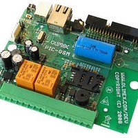
PIC-GSM Olimex Ltd., PIC-GSM Datasheet - Page 20

PIC-GSM
Manufacturer Part Number
PIC-GSM
Description
MCU, MPU & DSP Development Tools DEV BRD W/GSM MOD PIC18F97J60-I/PT
Manufacturer
Olimex Ltd.
Datasheet
1.PIC-GSM.pdf
(26 pages)
Specifications of PIC-GSM
Processor To Be Evaluated
PIC18F67J50
Data Bus Width
8 bit
Interface Type
Ethernet, USB, I2C, SPI, UART
Dimensions
100 mm x 80 mm
Operating Supply Voltage
5 V
Tool Type
Development Kit
Core Architecture
PIC
Cpu Core
PIC
Lead Free Status / RoHS Status
Lead free / RoHS Compliant
Other names
1772148 51R7061
MTX/DTX
MRX/DRX
J1,J2
Default state MTX
Default state MRX
Default state 1-2
The GSM module have two UART channels. One for the
commands, one for debugging. With this jumper you control
which channel goes to PIC18F97J60 or FT232RL.
The GSM module have two UART channels. One for the
commands, one for debugging. With this jumper you control
which channel goes to PIC18F97J60 or FT232RL.
These
communication port of the FT232RL chip to the MTX/DTX
controller or to the SIM300D module. Default configuration is
SIM300D module to communicates with FT232RL chip, but if
you wish to use USART communication option of Microchip
TCP/IP stack, you can switch J1 and J2 jumpers. When J1
and J2 jumpers are to 1-2 state - serial communication from
FT232RL chip is connected to the GSM module. You can use
virtual com port for communication with GSM module. The
PIC18F97J60 microcontroller however must release RXD and
TXD pins. When J1 and J2 jumpers are to 2-3 state - serial
communication from FT232RL chip is connected to the
PIC18F97J60 microcontroller. You can use virtual com port for
communication with PIC18F97J60. MTX/DTX and MRX/DRX
jumpers however must be open and you can not communicate
with GSM module.
jumpers
allow
1 2 3
MRX/DRX
MTX/DTX
to
switch
the
virtual
RS232


