PIC-GSM Olimex Ltd., PIC-GSM Datasheet - Page 21
PIC-GSM
Manufacturer Part Number
PIC-GSM
Description
MCU, MPU & DSP Development Tools DEV BRD W/GSM MOD PIC18F97J60-I/PT
Manufacturer
Olimex Ltd.
Datasheet
1.PIC-GSM.pdf
(26 pages)
Specifications of PIC-GSM
Processor To Be Evaluated
PIC18F67J50
Data Bus Width
8 bit
Interface Type
Ethernet, USB, I2C, SPI, UART
Dimensions
100 mm x 80 mm
Operating Supply Voltage
5 V
Tool Type
Development Kit
Core Architecture
PIC
Cpu Core
PIC
Lead Free Status / RoHS Status
Lead free / RoHS Compliant
Other names
1772148 51R7061


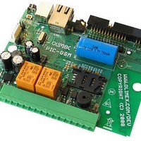
INPUT/OUTPUT:
LAN: RJ45 isolated ethernet connector. You can connect to PC host(with
crossed cable), router or ethernet switch. The default IP address is:
192.168.0.105. The main page properties are described in software section.
Button B1: user button connected to PIC18F97J60 pin.6 RB1 (INT1);
PWRKEY button – This is GSM module power on/off key. When the module
is ON if you press and hold for more than 3 seconds the module go in
power down state. If the module if in power down mode and you press and
hold this key for more than 1 second the module will go in ON mode.
MIC – on-board microphone (voice), with AT command you can switch the
voice audio input to be taken from this microphone of from the handsfree
audio connector.
SPEAKER – voice output for external 32 ohm speaker, with AT command
you can switch the voice audio output to be directed to this speaker or to
the handsfree audio connector.
HANDSFREE – audio 2.5 mm jack microphone input and speaker output.
BUZ – audio buzzer , can be used as RING signalization.
Status green LED with name LED connected to PIC18F97J60 pin.11 RG5.
Status red LED with name STAT – indicates the state of GSM module.
STAT is off state – GSM module is not running
64ms On/ 800ms Off – GSM module does not find the network
64ms On/ 3000ms Off – GSM module is connected to the network
64ms On/ 300ms Off - GPRS communication
Optocouple 1 – OPT1 (H11A817SMD) - 5V-12V optoisolated input with
LED2 indication and open collector output connect to PIC18F97J60 pin.51
(CCP4/P3D). Positive voltage of '+' terminal and negative voltage or GND of
'-' terminal of OPT_TEMP connector, reflect with log. 0 of PIC18F97J60
input.
Optocouple 2 – OPT2 (H11A817SMD) - 5V-12V optoisolated input with
LED3 indication and open collector output connect to PIC18F97J60 pin.14
(PG4/CCP5/P1D).Positive voltage of '+' terminal and negative voltage or
GND of '-' terminal of OPT_TEMP connector, reflect with log. 0 of
PIC18F97J60 input.
Relay1 – REL1 240VAC/10A (RAS1215) with default tied Normal Close (NC)
and COM terminals and disconnected Normal Open and COM terminals.
LED_R1 (Red) indicated when turn on REL1. The relay is turned on with
log 1 of PG7 port.
Relay2 – REL2 240VAC/10A (RAS1215) with default tied Normal Close (NC)
and COM terminals and disconnected Normal Open and COM terminals.
LED_R2 (Red) indicated when turn on REL2. The relay is turned on with
log 1 of PG6 port.
Related parts for PIC-GSM
Image
Part Number
Description
Manufacturer
Datasheet
Request
R

Part Number:
Description:
MCU, MPU & DSP Development Tools MPLAB 8/18/28/40P FOR PICSTART+
Manufacturer:
Olimex Ltd.

Part Number:
Description:
MCU, MPU & DSP Development Tools DEV BRD FOR 28 PIN MICRO CONT
Manufacturer:
Olimex Ltd.
Datasheet:

Part Number:
Description:
MCU, MPU & DSP Development Tools PROTOTYPE BRD FOR 40 PIN PIC
Manufacturer:
Olimex Ltd.
Datasheet:

Part Number:
Description:
MCU, MPU & DSP Development Tools PROTOTYPE BRD ICSP/ ICD ENABLED 28 PIN
Manufacturer:
Olimex Ltd.
Datasheet:

Part Number:
Description:
MCU, MPU & DSP Development Tools PROTOTYPE BRD ICSP/ ICD ENABLED 14 PIN
Manufacturer:
Olimex Ltd.
Datasheet:

Part Number:
Description:
MCU, MPU & DSP Development Tools PROTOTYPE BRD FOR 28 PIN PIC
Manufacturer:
Olimex Ltd.
Datasheet:

Part Number:
Description:
Development Boards & Kits - PIC / DSPIC MINI PROTOTYPE BRD FOR 8 PIN PIC
Manufacturer:
Olimex Ltd.

Part Number:
Description:
MCU, MPU & DSP Development Tools TCP-IP DEV BRD FOR PIC18F67J60
Manufacturer:
Olimex Ltd.
Datasheet:

Part Number:
Description:
MCU, MPU & DSP Development Tools PROTOTYPE BRD ICSP/ ICD ENABLED 40 PIN
Manufacturer:
Olimex Ltd.
Datasheet:

Part Number:
Description:
MCU, MPU & DSP Development Tools PROTOTYPE BRD FOR PIC18F67J60
Manufacturer:
Olimex Ltd.
Datasheet:

Part Number:
Description:
Microcontroller & Microprocessor Development Tools TCP-IP DEV BRD PIC32MX460F512
Manufacturer:
Olimex Ltd.
Datasheet:

Part Number:
Description:
Microcontroller & Microprocessor Development Tools PROTOTYPE BOARD TMS320F28027
Manufacturer:
Olimex Ltd.
Datasheet:

Part Number:
Description:
Microcontroller & Microprocessor Development Tools HDR BRD FOR LPC3131
Manufacturer:
Olimex Ltd.
Datasheet:

Part Number:
Description:
Microcontroller & Microprocessor Development Tools MP3 PLYR MOD WITH VS1002
Manufacturer:
Olimex Ltd.
Datasheet:
Part Number:
Description:
Microcontroller & Microprocessor Development Tools MP3 PLYR MOD BAT WITH VS1002
Manufacturer:
Olimex Ltd.
Datasheet: