II-EVB-363ML-110 Connect One, II-EVB-363ML-110 Datasheet - Page 26
II-EVB-363ML-110
Manufacturer Part Number
II-EVB-363ML-110
Description
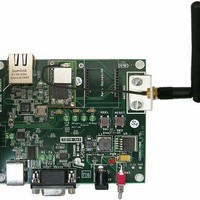
WiFi / 802.11 Modules & Development Tools Nano LANReach Evaluation Board
Manufacturer
Connect One
Datasheet
1.II-EVB-363MW-US-110.pdf
(27 pages)
Specifications of II-EVB-363ML-110
Interface Type
RS-232, USB
Security
64/128 bit WEP, AES-CCM, TKIP, WPA, WPA2
Operating Voltage
9 VDC
Lead Free Status / RoHS Status
Lead free / RoHS Compliant


Connect One
Appendix 6: SPI Host Interface
Introduction
The Nano WiReach contains an SPI slave port, which allows a Host processor to
interface the iChip using an SPI Master port.
The SPI data transfer shall be based on the 'Command-Response' principle. (Half
Duplex). Meaning, until the HOST gets an answer to a command, it won't send a
new one.
Several assumptions have been made:
The SPI interface will have the following behavior:
SPI Protocol
A Nano WiReach GPIO Output signal is dedicated as the SPI Control signal
(nSPI_INT). After receiving a command from the Host, Nano WiReach will assert
this signal for the duration of its response. The Host should not attempt to send the
next command until this signal is de-asserted. The SPI control signal pin is defined
with the new +iSPIP parameter described below.
The SPI control signal is also utilized as a flow-control signal when the Host transmits
data to the Nano WiReach.
Data from Nano WiReach to Host (Slave to Master)
When Nano WiReach replies to the Host commands it sends data packets preceded by
a 2-byte header using the following structure:
II-EVB-363NW User’s Manual
• Number of bits per transfer is: 8.
• No echo from the Nano WiReach to HOST (i.e. when Nano WiReach’s
• When Nano WiReach’s host interface is set to SPI, Nano WiReach won't
• When Nano WiReach’s host interface is set to SPI, Nano WiReach won't
• Fixed peripheral select
• The CS is directly connected to the SPI Master device
• Mode fault detection is enabled
• The inactive state value of the serial clock is logic level zero
• Data is changed on the leading edge of the serial clock and captured on the
• The peripheral chip select line rises as soon as the last transfer is achieved
Bit 15 is the Data-Ready bit
host interface is set to SPI, the command AT+iEn is meaningless.
support SerialNet mode since it is not Half Duplex compatible.
support the “+++” Escape sequence.
following edge of the serial clock
1
0
0
0
4bits MSB
12bits Data Length
8bits LSB
26
Related parts for II-EVB-363ML-110
Image
Part Number
Description
Manufacturer
Datasheet
Request
R

Part Number:
Description:
Ethernet Modules & Development Tools iChipSec CO2128 Eval Board -EU
Manufacturer:
Connect One
Datasheet:
Part Number:
Description:
MCU, MPU & DSP Development Tools iChip CO2464SEC EVAL BOARD 220V
Manufacturer:
Connect One
Datasheet:

Part Number:
Description:
WiFi / 802.11 Modules & Development Tools EvalBrd NanoSoktWiFi EU 220V Pwr Supply
Manufacturer:
Connect One
Datasheet:
Part Number:
Description:
WiFi / 802.11 Modules & Development Tools EvalBrd NanoSoktWiFi USA 110V Pwr Supply
Manufacturer:
Connect One
Datasheet:

Part Number:
Description:
WiFi / 802.11 Modules & Development Tools Nano SocketLAN Evaluation Board
Manufacturer:
Connect One
Datasheet:
Part Number:
Description:
WiFi / 802.11 Modules & Development Tools Eval board for Sec Socket iWiFi MS EU
Manufacturer:
Connect One
Datasheet:
Part Number:
Description:
WiFi / 802.11 Modules & Development Tools Eval Brd for Mini- Socket iWiFi MS
Manufacturer:
Connect One
Datasheet:
Part Number:
Description:
Nano WiReach+LANReach Evaluation Board-Europe
Manufacturer:
Connect One
Part Number:
Description:
Nano WiReach Evaluation Board-Europe
Manufacturer:
Connect One
Part Number:
Description:
Evaluation board for Nano WiReach SMT
Manufacturer:
Connect One
Part Number:
Description:
WiFi / 802.11 Modules & Development Tools EVB FOR MINISOCKET iWiFi MOD USA 110V
Manufacturer:
Connect One
Datasheet:
Part Number:
Description:
Ethernet Modules & Development Tools iChipSec CO2128 Eval Board -US
Manufacturer:
Connect One
Datasheet:
Part Number:
Description:
Ethernet Modules & Development Tools CO2064 Eval Board Inst Internet 3.3V
Manufacturer:
Connect One
Datasheet:
Part Number:
Description:
WiFi / 802.11 Modules & Development Tools Nano WiReach Eval Board-US
Manufacturer:
Connect One
Datasheet:
Part Number:
Description:
WiFi / 802.11 Modules & Development Tools Nano LANReach Evaluation Board
Manufacturer:
Connect One
Datasheet: