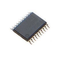
MAX1441GUP/V+ Maxim Integrated Products, MAX1441GUP/V+ Datasheet - Page 27

MAX1441GUP/V+
Manufacturer Part Number
MAX1441GUP/V+
Description
Touch Screen Converters & Controllers PROXIMITY SENSR el Proximity and Tou
Manufacturer
Maxim Integrated Products
Datasheet
1.MAX1441GUPV.pdf
(41 pages)
Specifications of MAX1441GUP/V+
Lead Free Status / RoHS Status
Lead free / RoHS Compliant
Table 11. Special-Function Register Bit Description (continued)
SCT (01h, 01h)
Initialization
Read/Write Access
SCT.0–SCT
SCT.1–SCEN
SCT[7:2]
CRNG (02h, 01h)
Initialization
Read/Write Access
CRNG[1:0]–
CRNG1[1:0]
CRNG[3:2]
CRNG[5:4]–
CRNG2[1:0]
CRNG[7:6]
PD (03h, 01h)
Initialization
Read/Write Access
PD.0–SB
PD.1–PD1
PD.2–PD2
PD[7:3]
WU1 (04h, 01h)
Initialization
Read/Write Access
WU1.0–AE1
REGISTER
Automotive, Two-Channel Proximity and
Single Conversion Register (8-Bit Register)
This register is cleared to 02h on all forms of reset.
Unrestricted read/write. See the following individual bit definitions for write restriction.
Single Conversion Trigger. Setting this bit to 1 initiates a conversion to an enabled channel (PDx = 0)
when the single conversion mode is enabled. Once set to 1, a write to this bit is ignored. This bit is
automatically cleared to 0 at the end of the conversion.
Single Conversion Enable. Setting this bit to 1 enables the single conversion mode. Clearing this bit to
0 disables the single conversion mode.
Reserved. Read returns 0.
Input Range Register (8-Bit Register)
This register is cleared to 22h on all forms of reset.
Unrestricted read/write.
CH1 Capacitance Input Range Bits [1:0]. These bits set the capacitance input range.
Reserved. Read returns 0.
CH2 Capacitance Input Range Bits [1:0]. These bits set the capacitance input range.
Reserved. Read returns 0.
Power-Down Register (8-Bit Register)
This register is cleared to 0000h on all forms of reset.
Unrestricted read. Write to this register is unrestricted, unless otherwise stated in the following bit
definition.
Standby Enable. Setting this bit to 1 enables the standby mode for both channels. Clearing this bit to 0
disables the standby mode. When standby mode is enabled, the conversion occurs at a divided-down
rate as defined by DSB and SSB. Once set, this bit can be cleared by software. This bit is automatically
cleared to 0 if a wake-up event occurs.
CH1 Power-Down. Setting this bit to 1 powers down CH1. Clearing this bit to 0 powers up CH1.
CH2 Power-Down. Setting this bit to 1 powers down CH2. Clearing this bit to 0 powers up CH2.
Reserved. Read returns 0.
CH1 Wake-Up Control Register (8-Bit Register)
This register is cleared to 04h on all forms of reset.
Unrestricted read/write.
CH1 Absolute Wake-Up Threshold Enable. Setting this bit to 1 enables the absolute wake-up
threshold detection. Clearing this bit to 0 disables the absolute wake-up threshold detection.
CRNG1[1:0]
CRNG2[1:0]
00
01
10
11
00
01
10
11
DESCRIPTION
CAPACITANCE RANGE (pF)
CAPACITANCE RANGE (pF)
10
20
20
10
20
20
5
5
Touch Sensor
27


