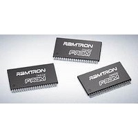
FM22L16-55-TG Ramtron, FM22L16-55-TG Datasheet - Page 8

FM22L16-55-TG
Manufacturer Part Number
FM22L16-55-TG
Description
F-RAM 4M (256Kx16) 55ns
Manufacturer
Ramtron
Datasheet
1.FM22L16-55-TG.pdf
(15 pages)
Specifications of FM22L16-55-TG
Organization
256 Kbit x 16
Access Time
55 ns
Operating Supply Voltage
2.7 V to 3.6 V
Operating Temperature Range
- 40 C to + 85 C
Mounting Style
SMD/SMT
Memory Size
4 Mbit
Interface
Parallel
Package / Case
TSOP-44
Lead Free Status / RoHS Status
Lead free / RoHS Compliant
Available stocks
Company
Part Number
Manufacturer
Quantity
Price
Company:
Part Number:
FM22L16-55-TG
Manufacturer:
RAM
Quantity:
15
Part Number:
FM22L16-55-TG
Manufacturer:
RAMTRON
Quantity:
20 000
Part Number:
FM22L16-55-TGKJ
Manufacturer:
CYPRESS/赛普拉斯
Quantity:
20 000
Company:
Part Number:
FM22L16-55-TGTR
Manufacturer:
CYPRESS
Quantity:
15 000
SRAM Drop-In Replacement
The FM21L16 has been designed to be a drop-in
replacement for standard asynchronous SRAMs. The
device does not require /CE to toggle for each new
address. /CE may remain low for as long as 10µs.
While /CE is low, the device automatically detects
address changes and a new access is begun. It also
allows page mode operation at speeds up to 33MHz.
The user must be sure /CE is not low at powerup
or powerdown events. If /CE and /WE are both
low during power cycles, data corruption will
occur. Figure 6 shows a pullup resistor on /CE
which will keep the pin high during power cycles
assuming the MCU/MPU pin is tri-stated during
the system reset. The pullup resistor value should
be chosen to ensure the /CE pin tracks V
high enough value that the current drawn when
/CE is low is not an issue. A 10K ohm resistor
draws 330µA when /CE is low and V
For applications that require the lowest power
consumption, the /CE signal should be active (low)
Rev. 2.0
Apr. 2011
MCU/
Figure 6. Use of Pullup Resistor on /CE
MPU
R
V
DD
FM21L16
DD
CE
WE
OE
A(16:0)
DQ
=3.3V.
DD
yet a
only during memory accesses. The FM21L16 draws
supply current while /CE is low, even if addresses and
control signals are static. While /CE is high, the
device draws no more than the maximum standby
current I
The FM21L16 is backward compatible with the
1Mbit FM20L08 and 256Kbit FM18L08 devices.
That is, operating the FM21L16 with /CE toggling
low on every address is perfectly acceptable.
The /UB and /LB byte select pins are active for both
read and write cycles. They may be used to allow the
device to be wired as a 256Kx8 memory. The upper
and lower data bytes can be tied together and
controlled with the byte selects. Individual byte
enables or the next higher address line A(17) may be
available from the system processor.
Figure 7. FM21L16 Wired as 256Kx8
SB
.
FM21L16 - 128Kx16 FRAM
Page 8 of 15


