AGL400V5-FGG484 Actel, AGL400V5-FGG484 Datasheet - Page 82
AGL400V5-FGG484
Manufacturer Part Number
AGL400V5-FGG484
Description
FPGA - Field Programmable Gate Array 400K System Gates
Manufacturer
Actel
Datasheet
1.AGL030V2-CSG81.pdf
(236 pages)
Specifications of AGL400V5-FGG484
Processor Series
AGL400
Core
IP Core
Number Of Logic Blocks
12
Maximum Operating Frequency
250 MHz
Number Of Programmable I/os
194
Data Ram Size
54 Kbit
Supply Voltage (max)
1.5 V
Supply Current
27 uA
Maximum Operating Temperature
+ 70 C
Minimum Operating Temperature
0 C
Development Tools By Supplier
AGL-Icicle-Kit, AGL-Dev-Kit-SCS, Silicon-Explorer II, Silicon-Sculptor 3, SI-EX-TCA, FlashPro 4, FlashPro 3, FlashPro Lite
Mounting Style
SMD/SMT
Supply Voltage (min)
1.425 V
Number Of Gates
400 K
Package / Case
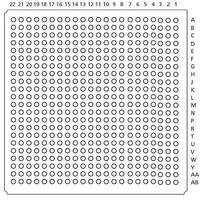
FPBGA-484
Lead Free Status / RoHS Status
Lead free / RoHS Compliant
Available stocks
Company
Part Number
Manufacturer
Quantity
Price
Company:

Part Number:
AGL400V5-FGG484
Manufacturer:
Actel
Quantity:
135
Company:
Part Number:
AGL400V5-FGG484
Manufacturer:
Microsemi SoC
Quantity:
10 000
Company:
Part Number:
AGL400V5-FGG484I
Manufacturer:
Microsemi SoC
Quantity:
10 000


IGLOO DC and Switching Characteristics
Table 2-110 • Minimum and Maximum DC Input and Output Levels
Table 2-111 • Minimum and Maximum DC Input and Output Levels
2- 68
1.5 V
LVCMOS
Drive
Strength
2 mA
4 mA
6 mA
8 mA
12 mA
Notes:
1. I
2. I
3. Currents are measured at 100°C junction temperature and maximum voltage.
4. Currents are measured at 85°C junction temperature.
5. Software default selection highlighted in gray.
1.5 V
LVCMOS
Drive
Strength
2 mA
4 mA
Notes:
1. I
2. I
3. Currents are measured at 100°C junction temperature and maximum voltage.
4. Currents are measured at 85°C junction temperature.
5. Software default selection highlighted in gray.
larger when operating outside recommended ranges
larger when operating outside recommended ranges
IL
IH
IL
IH
is the input leakage current per I/O pin over recommended operation conditions where –0.3 V < VIN < VIL.
is the input leakage current per I/O pin over recommended operation conditions where –0.3 V < VIN < VIL.
is the input leakage current per I/O pin over recommended operating conditions VIH < VIN < VCCI. Input current is
is the input leakage current per I/O pin over recommended operating conditions VIH < VIN < VCCI. Input current is
Min.
–0.3
–0.3
Min.
–0.3 0.35 * VCCI 0.65 * VCCI 1.575
–0.3 0.35 * VCCI 0.65 * VCCI 1.575
–0.3 0.35 * VCCI 0.65 * VCCI 1.575
–0.3 0.35 * VCCI 0.65 * VCCI 1.575
–0.3 0.35 * VCCI 0.65 * VCCI 1.575
1.5 V LVCMOS (JESD8-11)
Low-Voltage CMOS for 1.5 V is an extension of the LVCMOS standard (JESD8-5) used for general-
purpose 1.5 V applications. It uses a 1.5 V input buffer and a push-pull output buffer.
V
Applicable to Advanced I/O Banks
V
Applicable to Standard Plus I/O Banks
VIL
0.35 * VCCI 0.65 * VCCI 1.575
0.35 * VCCI 0.65 * VCCI
VIL
Max.
Max.
V
V
Min.
Min.
V
V
VIH
VIH
Max.
1.575
Max.
V
V
0.25 * VCCI
0.25 * VCCI
0.25 * VCCI
0.25 * VCCI
0.25 * VCCI
0.25 * VCCI 0.75 * VCCI
0.25 * VCCI 0.75 * VCCI
R ev i sio n 1 8
Max.
V
V
Max.
VOL
OL
V
0.75 * VCCI
0.75 * VCCI
0.75 * VCCI
0.75 * VCCI
0.75 * VCCI 12 12
VOH
Min.
VOH
Min.
V
V
mA mA
mA mA
I
I
OL
OL
6
8
2
4
2
4
I
I
OH
OH
6
8
2
4
2
4
Max.
mA
I
Max.
OSH
I
mA
13
25
OSH
13
25
32
66
66
3
3
Max.
mA
I
Max.
mA
OSL
I
16
33
OSL
16
39
55
55
33
3
3
µA
µA
I
I
10 10
10 10
10 10
10 10
10 10
IL
10 10
10 10
IL
1
1
4
4
µA
µA
I
I
IH
IH
2
2
4
4
Related parts for AGL400V5-FGG484
Image
Part Number
Description
Manufacturer
Datasheet
Request
R

Part Number:
Description:
PBGA 196/FPGA, 9216 CLBS, 400000 GATES
Manufacturer:
Actel

Part Number:
Description:
FPGA - Field Programmable Gate Array 400K System Gates
Manufacturer:
Actel
Datasheet:

Part Number:
Description:
FPGA - Field Programmable Gate Array 400K System Gates
Manufacturer:
Actel
Datasheet:
Part Number:
Description:
FPGA - Field Programmable Gate Array 400K System Gates
Manufacturer:
Actel
Datasheet:

Part Number:
Description:
FPGA - Field Programmable Gate Array 400K System Gates
Manufacturer:
Actel
Datasheet:
Part Number:
Description:
MCU, MPU & DSP Development Tools Silicon Sculptor Programming Mod
Manufacturer:
Actel
Part Number:
Description:
MCU, MPU & DSP Development Tools InSystem Programming ProASICPLUS Devices
Manufacturer:
Actel
Part Number:
Description:
Programming Socket Adapters & Emulators PQ160 Module
Manufacturer:
Actel
Part Number:
Description:
Programming Socket Adapters & Emulators Axcelerator Adap Module Kit
Manufacturer:
Actel
Part Number:
Description:
Programming Socket Adapters & Emulators Evaluation
Manufacturer:
Actel