GRF172D-5 TELEDYNE, GRF172D-5 Datasheet - Page 4
GRF172D-5
Manufacturer Part Number
GRF172D-5
Description
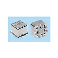
RF (Radio Frequency) Relays 5V DC-6GHz .15W w/diode
Manufacturer
TELEDYNE
Series
GRF172r
Specifications of GRF172D-5
Coil Current
0.15 W
Frequency
6 GHz
Contact Form
2 Form C (DPDT)
Coil Voltage
5 VDC
Power Consumption
405 mW
Termination Style
SMD/SMT
Brand/series
GRF172D Series
Capacitance
0.4 pF (Typ.) (Intercontact)
Current, Rating
1 A
Diameter, Body
0.370 in. (Max.)
Diameter, Lead
0.017 in.
Function
Frequency (RF)
Height
0.330 in. (Max.)
Length, Lead
0.033 in.
Mounting Type
PCB
Number Of Pins
8
Package Type
TO-5
Relay Type
Electro Mechanical
Resistance, Coil
64 Ohms +⁄- 20%
Resistance, Contact
0.15 Ohms (Max.) (Before Life), 0.3 Ohms (Max.) (After Life) @ 1 A⁄28 VDC
Temperature, Operating
-55 to +85 °C
Termination
Surface Mount
Voltage, Control
5 VDC
Voltage, Rating
28 VDC
Lead Free Status / RoHS Status
Lead free / RoHS Compliant


Page 4 GRF172
SERIES GRF172
GENERAL ELECTRICAL SPECIFICATIONS (@25°C Notes 2 & 5)
DETAILED ELECTRICAL SPECIFICATIONS (@25°C Note 2)
GENERAL NOTES
1. Relays will exhibit no contact chatter in
2. Unless otherwise specified, parameters
3. Relays may be subjected to 260°C,
4. Butt-lead ends are coplanar within
5. “Typical” characteristics are based on
6. Application notes available for PCB
Contact Arrangement
Rated Duty
Contact Resistance
Contact Load Rating (DC)
(See Fig. 1 for other DC
resistive voltage/current
ratings)
Contact Life Ratings
Contact Overload Rating
Contact Carry Rating
Operate Time
Release Time
Intercontact Capacitance
Insulation Resistance
Dielectric Strength
Negative Coil Transient GRF172
Diode P.I.V. GRF172D
Coil Voltage, Nominal (Vdc)
Coil Resistance (Ohms ±20%)
Pick-up Voltage (Vdc, Max.)
Coil Operating Power at Nominal Voltage (Milliwatts)
excess of 10 µsec or transfer in excess
of 1 µsec.
are initial values.
peak solder reflow temperature, 1
minute, 3 passes.
.003" (0.08).
available data and are best estimates.
No on-going verification tests are
performed.
layout and mounting information.
2 Form C (DPDT)
Continuous
0.15 ohm max. before life; 0.3 ohm max. after life at 1A/28Vdc (measured 1/8" from header)
Resistive:
Inductive:
Lamp:
Low Level:
2A/28Vdc Resistive (100 cycles min.)
Contact factory
6.0 msec max. at nominal rated coil voltage
GRF172: 3.0 msec max.
0.4 pf typical
1,000 megohms min. between mutually isolated terminals
Atmospheric pressure: 350 Vrms/60Hz
2.0 Vdc Max.
60 Vdc Min.
SPECIFICATIONS ARE SUBJECT TO CHANGE WITHOUT NOTICE
5,000,000 cycles (typical) at low level
500,000 cycles (typical) at 0.5A/28Vdc resistive
100,000 cycles min. at all other loads specified above
BASE PART
NUMBERS
1 Amp/28Vdc
100 mA/28Vdc (320 mH)
100 mA/28Vdc
10 to 50 µA/10 to 50mV
OUTLINE DIMENSIONS
Nom.
Max.
www.teledynerelays.com
.100 TYP
.031 REF
(2.54)
GRF172D: 6.0 msec max.
.330 MAX
(0.79)
(8.38)
NOTES:
1. DIMENSIONS ARE IN INCHES. METRIC EQUIVALENTS IN MILLIMETERS ARE SHOWN IN ( ).
2. UNLESS OTHERWISE SPECIFIED, TOLERANCES ON DIMENSIONS ARE ±.010 INCH (0.025 mm).
3. FOR OPTIMAL RF PERFORMANCE, SOLDER BOTTOM OF GROUND SHIELD TO PCB RF GROUND PLANE.
GRF172D-5
GRF172-5
.100 TYP
(2.54)
405
5.0
5.8
3.8
64
U.S. PATENT PENDING
SEE NOTE 3.
.375 SQ
(9.531)
.035 REF
MAX
(0.89)
GRF172D-12
GRF172-12
.033 (0.84) REF
SCHEMATIC IS VIEWED FROM TERMINALS
LENGTH
SCHEMATIC-TERMINAL VIEW
12.0
16.0
400
360
9.0
SCHEMATIC IS VIEWED FROM TERMINALS
6
5
6
5
7
7
NOT MARKED ON RELAY.
FOR REFERENCE ONLY,
.335 SQ
(8.51)
PIN NUMBERS ARE
MAX
8 LEADS
GRF172D
GRF172
8
8
(0.43)
.017
4
4
©2004 TELEDYNE RELAYS
DIA.
+.002
+0.05
-.001
-0.03
3
3
1
2
1
2
GRF172D-26
GRF172-26
(0.89)
.035 REF
1600
26.5
32.0
18.0
GRF172/0204/Q1
440
Related parts for GRF172D-5
Image
Part Number
Description
Manufacturer
Datasheet
Request
R

Part Number:
Description:
RF (Radio Frequency) Relays 12V DC-6GHz .15W
Manufacturer:
TELEDYNE
Datasheet:
Part Number:
Description:
RF (Radio Frequency) Relays 5V DC-6GHz .15W
Manufacturer:
TELEDYNE
Datasheet:

Part Number:
Description:
Relay; E-Mech; Freq (RF); DPDT; Cur-Rtg 1A; Ctrl-V 5DC; Vol-Rtg 28DC; PCB Mnt; 10 Pin
Manufacturer:
TELEDYNE
Datasheet:
Part Number:
Description:
Module; Thru Hole; Solid-State; 3.5 mA @ 115 V (RMS), 3.0 mA @ 220 V (RMS); 7
Manufacturer:
TELEDYNE
Datasheet:
Part Number:
Description:
Module; Thru Hole; Solid-State; 15 mA (Max.); 3.8 to 16 V (RMS); 3 VDC (Min.)
Manufacturer:
TELEDYNE
Datasheet:
Part Number:
Description:
Relay; Hybrid; Freq (RF); DPDT; Cur-Rtg 1A; Ctrl-V 12DC; Vol-Rtg 28DC; PCB Mnt
Manufacturer:
TELEDYNE
Datasheet: