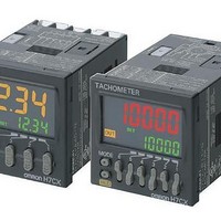
H7CX-AWD1-N DC12-24 AC24 Omron, H7CX-AWD1-N DC12-24 AC24 Datasheet - Page 9

H7CX-AWD1-N DC12-24 AC24
Manufacturer Part Number
H7CX-AWD1-N DC12-24 AC24
Description
Tachometers CntOut SPST+SPDT 12V 2Stage 6Digit Tchmtr
Manufacturer
Omron
Type
1 or 2 State, Total and Preset Counterbatch, Dual/Twin Counterr
Datasheet
1.H7CX-A-N_AC100-240.pdf
(56 pages)
Specifications of H7CX-AWD1-N DC12-24 AC24
Frequency Response
50 Hz
Product
Panel Mount Tachometer
Voltage
12 VDC to 24 VDC, 24 VAC
Display Type
6 Digit
Accuracy
+/- 0.1 %
Lead Free Status / RoHS Status
Lead free / RoHS Compliant
Other names
H7CXAWD1NDC1224/AC24
Block Diagram
Note: All models except for H7CX-@D-N have basic insulation.
Input Connections
The inputs of the H7CX-@-N are no-voltage (short-circuit or open) inputs or voltage inputs.
No-voltage Inputs (NPN Inputs)
Open Collector
No-voltage Input Signal Levels
Note: The DC voltage must be 30 VDC max.
Voltage Inputs (PNP Inputs)
No-contact Input (NPN Transistor)
Voltage Input Signal Levels
Note: 1. The DC voltage must be 30 VDC max.
No-contact input
Contact input
High level (input ON): 4.5 to 30 VDC
Low level (input OFF): 0 to 2 VDC
Note: Operates with transistor ON.
H7CX-A@
H7CX-A11@
Input circuits
(Basic insulation)
2. Input resistance: Approx. 4.7 k
Output circuit
Note: Operates with transistor OFF.
PLC or
sensor
H7CX-A@
H7CX-A11@
Sensor
6
3
(Basic insulation)
Short-circuit level (transistor ON)
• Residual voltage: 3 V max.
• Impedance when ON: 1 k
Open level (transistor OFF)
• Impedance when OFF: 100 k
Use contacts which can adequately switch 5 mA at 10 V.
control circuit
7
7
(The leakage current is approx. 12 mA when the impedance is 0 .)
Internal
6
3
8
5
7
7
9
6
8
5
10
(See note.)
4
Power supply
9
6
circuit
Display circuit
Voltage Output
Key switch
10
4
Note: Operates with transistor ON.
circuit
H7CX-A@
H7CX-A11@
Sensor
max.
min.
No-contact Input (PNP Transistor)
6
3
7
7
Note: Operates with transistor ON.
H7CX-A@
H7CX-A11@
8
5
Sensor
9
6
10
4
6
3
Contact Input
7
7
Note: Operates with relay ON.
H7CX-A@
H7CX-A11@
Input Circuits
CP1, CP2, Reset/Reset 1, and Total Reset/Reset 2
Input
No-voltage Inputs
(NPN Inputs)
8
5
IN
9
6
10
4
6
3
7
7
1 k
+14V
8
5
Contact Input
Internal
circuit
9
6
10
4
Note: Operates with relay ON.
H7CX-A@
H7CX-A11@
DC Two-wire Sensor
• Leakage current: 1.5 mA max.
• Switching capacity: 5 mA min.
• Residual voltage: 3 VDC max.
• Operating voltage: 10 VDC
Voltage Inputs (PNP Inputs)
Note: Operates with transistor ON.
H7CX-A@
H7CX-A11@
Applicable Two-wire Sensor
IN
Approx. 4.7 k
6
3
7
7
H7CX-A@-N
6
3
8
5
7
7
9
6
8
5
10
4
Internal
circuit
9
6
10
4
9


