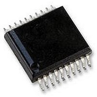
USB-FILESYS-SS HEXWAX, USB-FILESYS-SS Datasheet - Page 3

USB-FILESYS-SS
Manufacturer Part Number
USB-FILESYS-SS
Description
DRIVERFREE USB CONFIGURATION, 20SSOP
Manufacturer
HEXWAX
Datasheet
1.USB-FILESYS-DIL.pdf
(10 pages)
Specifications of USB-FILESYS-SS
Usb Type
FAT File System
Usb Version
2.0
No. Of Ports
1
Supply Voltage Range
1.8V To 5.5V
Operating Temperature Range
-40°C To +85°C
Digital Ic Case Style
SSOP
No. Of Pins
20
Package /
RoHS Compliant
MOSI may be changed by the master. (This is also
known as Mode D or 0,0 operation.) See figure 3. The
actual commands are specified in the Host Commands
section.
All commands from the host are followed by a response
from USB-FileSys.
generate a response is indeterminate, USB-FileSys will
output bytes of value 0xFF until it can generate a valid
response. After issuing a command, the host should
repeatedly read data from USB-FileSys, waiting for a
byte with a value other than 0xFF. The Write File and
Set File Entry commands are each composed of two
such Command-Response exchanges.
USB-FileSys has been tested with SPI clock rates up to
1MHz.
Memory
Internal Memory
In order to maximize available storage space, the
internal memory is pre-formatted as a 16-sector FAT12
file system with 512 bytes per sector.
sectors are required for the file system and root
directories.) Reformatting by the PC is not permitted.
The root directory can contain up to 16 entries, including
the volume name.
multiple directory entries, they are not recommended.
The volume is normally supplied containing no files. If
ordered in 5K+ quantities, files may be pre-loaded.
To indicate to USB-FileSys that the internal memory
should be used, the SCK-M input should be pulled low.
Pages of internal memory may be erased and rewritten
approximately 100K times.
frequently, the greatest wear will occur in the FAT tables
and the directory entry. Therefore if a file is to be written
to frequently, its size should be fixed.
This option is only available for the 28-pin device.
TQFP and SSOP packages are available, but they are
not in general distribution.
information.
External Memory – 25AA1024
For
25AA1024
connected to the MISO-M, MOSI-M, SCK-M and SSn-M
lines.
SCK-M. The media detect input should be permanently
biased low.
p3 of 10
SCLK
MOSI
MISO
SSn
moderate
Hi-Z
A 4k7 pull-up resistor should be provided for
memory
Command
storage
...
...
26-Aug-10
Figure 3. SPI Timing Diagram
1MHz max
Since long file names require
Since the time generated to
(128kByte
applications,
Contact us for further
If file sizes change
storage)
Response
USB-FileSys / USB-Config
...
...
a
(4 of these
Microchip
may
Hi-Z
be
When first used, the memory will automatically be
formatted as a 16-sector FAT12 file system with 512
bytes per sector. The PC may re-format the drive if
required.
External Memory – SD card / integrated circuit
For large storage applications, an SD-compatible
memory of up to 1GB may be connected to the MISO-M,
MOSI-M, SCK-M and SSn-M lines. 4k7 pull-up resistors
should be provided for these lines, and also for unused
SD card I/O pins.
The memory can be a removable SD card or a SD-
compatible chip. If the memory is removable, the media
detect input should be connected to a switch to indicate
when the card is present. Devices with SD card readers
will be able to read the data on the SD card directly.
Memories larger than 1GB will be ignored, as will non-
standard memories which do not have block sizes of
512 bytes. San-Disk products are used for testing.
Pages of SD memory are typically wear-leveled, so
memory wear is not a great concern – memory wear can
be compensated for by using a larger memory.
example, for a given amount of data stored, a 1GB SD
card will last 10 times longer than a 100MB card.
This option is only available for the 28-pin device.
TQFP and SSOP packages are available, but they are
not in general distribution.
information.
Memory Integrity
With internal memory and 25AA1024 memory, power
loss during a write may result in corruption of data,
possibly requiring reformatting of the disk.
With external memory, power loss protection may or
may not be implemented by the memory itself.
If power is lost while a file is open, the file length
information in the directory entry may be incorrect, but
the data will be intact.
Application Circuits
The following circuits show a typical implementation of
the USB-FileSys.
shown in table 3.
R1-R3, R40-R44
C4, C6-C7
C2, C3
D1-D2
Label
LED1
R21
R6
T1
C1
C8
X1
Table 3. Suggested component values
HW149-8
Suggested component values are
P-channel Mosfet, e.g. NDS352P
12MHz parallel cut crystal
Low Vf switching diode
Light emitting diode
100nF capacitor
470nF capacitor
22pF capacitor
Contact us for further
470Ω resistor
1μF capacitor
Component
22k resistor
1k resistor
www.hexwax.com
For


