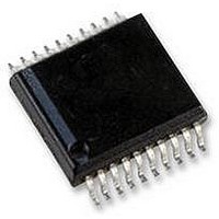
USB-FILESYS-SS HEXWAX, USB-FILESYS-SS Datasheet - Page 9

USB-FILESYS-SS
Manufacturer Part Number
USB-FILESYS-SS
Description
DRIVERFREE USB CONFIGURATION, 20SSOP
Manufacturer
HEXWAX
Datasheet
1.USB-FILESYS-DIL.pdf
(10 pages)
Specifications of USB-FILESYS-SS
Usb Type
FAT File System
Usb Version
2.0
No. Of Ports
1
Supply Voltage Range
1.8V To 5.5V
Operating Temperature Range
-40°C To +85°C
Digital Ic Case Style
SSOP
No. Of Pins
20
Package /
RoHS Compliant
With the 20-pin device, the next two bytes are the
number of bytes to write, up to a maximum of 64. The
write must not cross the 64-byte sector boundary.
Once the command has been sent, a response byte will
be received. Assuming this the Success response 0x00,
the data bytes are then sent. A second response byte
will then be received.
Note: Writes to files are permitted even if the read-only
bit is set in their directory entry; writes after the end of
the existing file may cause further clusters to be
allocated to the file.
Example:
Command:
Response:
Data:
Response:
Get Info
This command reads device information. The command
is the byte 0x0F. The first byte of the response is the
status byte. The second bytes indicates the information
in table 8. The third and fourth bytes are the version
number, least significant byte first.
Example:
Command:
Response:
p9 of 10
2-1
5-7
Bit
0E 02 23 01 00 00 04 00
00
01 02 03 04
00
0F
00 61 01 00
0
Meaning
Maximum current draw:
Activity pin function:
Cluster size:
(Read only – ignored with Set Info command)
0: Draw a maximum of 100mA from USB (default)
1: Draw a maximum of 500mA from USB
00: High for 100ms on any USB activity
10: High on PC write to any sector
11: High on PC write to root directory entry
000 - 512 bytes
001 - 1024 bytes
010 - 2048 bytes
011 - 4096 bytes
100 - 8192 bytes
101 - 16384 bytes
110 - 32768 bytes
Write 4 bytes at position 0123 on file
handle 02
Success, data is 12 34 56 78.
(01 02 03 04)
Success.
Get Info
Success, device is 500mA with a 4096-
byte cluster size, version 0001
Table 8. Info Flags
26-Aug-10
USB-FileSys / USB-Config
Set Info
This command sets the maximum current the device
may draw from the PC, and the function of the Activity
pin. The first byte of the command is the value 0x10.
The second is as specified in table 8. The response is
the status byte.
If USB-FileSys is configured for 500mA current draw, it
will only work when plugged directly into PCs and
powered hubs. The setting takes effect from the next
plug-in. In any event, the no more than 100μA should
be drawn if the PTO# pin is high.
Example:
Command:
Response:
Delivery and Programming
USB-FileSys is generally distributed in pre-programmed
in 28-pin DIL and 20-pin SSOP packages. Contact us
for other package options.
In high volumes (5K+), USB-FileSys is available reeled
with your custom settings preloaded, in any available
package.
TEAclipper Programming
For programming the firmware using TEAclipper/PIC HV,
the PGC, PGD and Vpp pins must be accessible.
During programming, these pins must be protected
against contention.
subject to up to 13V during programming. Nothing else
should be connected to Vpp except via a 22k pull-up
resistor.
The TEAclipper connector format is shown in figure 9.
Since
programming socket is required. The TEAclipper can be
‘leaned’ against the plate-through holes shown.
It is strongly recommended that this connector is
included in circuits even if in-circuit programming is not
anticipated, since this allows you to upgrade the
firmware if necessary.
Evaluation Board
The USB-Eval evaluation board is available for
evaluating USB-FileSys. Due to the variety of potential
implementations it is supplied unpopulated and a
prototyping area is provided. This will be necessary for
SD memory implementation. (e.g. Figure 10.)
Pin 1 indicated
by square pad
10 05
00
Figure 9. Recommended plate-through connector design
the
HW149-8
Set 500mA operation, activity on write
Success.
programming
In particular, note that Vpp is
2.54mm spacing
time
is
very
www.hexwax.com
1mm hole dia
fast,
no


