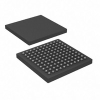
PIC32MX440F128L-80I/BG Microchip Technology, PIC32MX440F128L-80I/BG Datasheet - Page 40

PIC32MX440F128L-80I/BG
Manufacturer Part Number
PIC32MX440F128L-80I/BG
Description
IC, 32BIT MCU, PIC32, 80MHZ, BGA-100
Manufacturer
Microchip Technology
Series
PIC® 32MXr
Datasheets
1.MA320002.pdf
(208 pages)
2.DM320001.pdf
(44 pages)
3.PIC32MX320F032H-40IPT.pdf
(48 pages)
4.PIC32MX320F032H-40IPT.pdf
(66 pages)
5.PIC32MX320F032H-40IPT.pdf
(22 pages)
6.PIC32MX320F064H-40IMR.pdf
(172 pages)
Specifications of PIC32MX440F128L-80I/BG
Controller Family/series
PIC32
Ram Memory Size
32KB
Cpu Speed
80MHz
No. Of Timers
5
Interface
EUSART, I2C, SPI, USB
No. Of Pwm Channels
5
Core Size
32 Bit
Program Memory Size
128 KB
Core Processor
MIPS32® M4K™
Speed
80MHz
Connectivity
I²C, IrDA, LIN, PMP, SPI, UART/USART, USB OTG
Peripherals
Brown-out Detect/Reset, DMA, POR, PWM, WDT
Program Memory Type
FLASH
Ram Size
32K x 8
Voltage - Supply (vcc/vdd)
2.3 V ~ 3.6 V
Data Converters
A/D 16x10b
Oscillator Type
Internal
Operating Temperature
-40°C ~ 85°C
Package / Case
121-TFBGA
Embedded Interface Type
EUSART, I2C, SPI, USB
Rohs Compliant
Yes
Processor Series
PIC32MX4xx
Core
MIPS
Data Bus Width
32 bit
Data Ram Size
32 KB
Interface Type
EUART, I2C, SPI
Maximum Clock Frequency
80 MHz
Number Of Programmable I/os
85
Number Of Timers
5
Maximum Operating Temperature
+ 85 C
Mounting Style
SMD/SMT
3rd Party Development Tools
52713-733, 52714-737
Development Tools By Supplier
PG164130, DV164035, DV244005, DV164005, DM320003, DM320002, MA320002
Minimum Operating Temperature
- 40 C
On-chip Adc
10 bit, 16 Channel
Lead Free Status / RoHS Status
Lead free / RoHS Compliant
For Use With
876-1000 - PIC32 BREAKOUT BOARD
Number Of I /o
-
Eeprom Size
-
Lead Free Status / Rohs Status
Details
Available stocks
Company
Part Number
Manufacturer
Quantity
Price
Company:
Part Number:
PIC32MX440F128L-80I/BG
Manufacturer:
Microchip Technology
Quantity:
10 000
DS61144D-page 36
4.2.4
Push-button switches provide the following functionality:
• SW1: Active-low switch connected to RD6
• SW2: Active-low switch connected to RD7
• SW3: Active-low switch connected to RD13
The switches do not have any debounce circuitry and require the use of internal pull-
up resistors; this allows you to investigate debounce techniques. When Idle, the
switches are pulled high (+3.3V). When pressed, they are grounded.
4.2.5
The LEDs, RD0 through RD2, are connected to PORTD of the processor. The PORTD
pins are set high to light the LEDs.
4.2.6
The installed microcontroller has an oscillator circuit connected to it. The main oscillator
uses an 8 MHz crystal (Y2) and functions as the controller’s primary oscillator. Use of
an external crystal is not required for PIC32 designs. Your design may use the internal
oscillator, if desired.
The PIC18LF4550, at the heart of the USB subsystem, is independently clocked and
has its own 8 MHz crystal (Y1).
4.2.7
The PIC32MX Starter Kit demo board has been designed with a 120-pin modular
expansion interface, which allows the board to provide basic generic functionality now,
as well as easy extendability to new technologies as they become available.
TABLE 4-1:
Starter Board Connector
Application Board Connector
Switches
LEDs
Oscillator Options
120-Pin Modular Expansion Connector
Connector
STARTER BOARD CONNECTOR PART NUMBERS
FX10A-120P/12-SV1(71)
FX10A-120S/12-SV(71)
HIROSE Electric PN
© 2009 Microchip Technology Inc.


