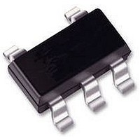
74HC1G66GW NXP Semiconductors, 74HC1G66GW Datasheet

74HC1G66GW
Specifications of 74HC1G66GW
Available stocks
Related parts for 74HC1G66GW
74HC1G66GW Summary of contents
Page 1
DATA SHEET 74HC1G66; 74HCT1G66 Bilateral switch Product specification Supersedes data of 2001 Mar 02 INTEGRATED CIRCUITS 2002 May 15 ...
Page 2
Philips Semiconductors Bilateral switch FEATURES Wide operating voltage range from 2.0 to 9.0 V Very low ON-resistance: – 45 (typical 4 – 30 (typical 6 – 25 (typical ...
Page 3
... Philips Semiconductors Bilateral switch ORDERING INFORMATION OUTSIDE NORTH TEMPERATURE AMERICA RANGE 74HC1G66GW 40 to +125 C 74HCT1G66GW 40 to +125 C 74HC1G66GV 40 to +125 C 74HCT1G66GV 40 to +125 C PINNING PIN SYMBOL GND handbook, halfpage GND MNA074 Fig.1 Pin configuration. 1 handbook, halfpage MNA076 Fig.3 IEC logic symbol. ...
Page 4
Philips Semiconductors Bilateral switch RECOMMENDED OPERATING CONDITIONS SYMBOL PARAMETER V supply voltage CC V input voltage I V switch voltage S T operating ambient amb temperature input rise and fall times r f LIMITING VALUES In accordance ...
Page 5
Philips Semiconductors Bilateral switch DC CHARACTERISTICS Family 74HC1G66 At recommended operating conditions; voltages are referenced to GND (ground = 0 V). SYMBOL PARAMETER V HIGH-level input IH voltage V LOW-level input IL voltage I input leakage LI current I analog ...
Page 6
Philips Semiconductors Bilateral switch Family 74HCT1G66 At recommended operating conditions; voltages are referenced to GND (ground = 0 V). SYMBOL PARAMETER V HIGH-level input IH voltage LOW-level input voltage input leakage current LI I analog switch current, ...
Page 7
Philips Semiconductors Bilateral switch Family 74HC1G66 and 74HCT1G66 For 74HC1G66 2.0, 4.5, 6.0 or 9.0 V; note 1. CC For 74HCT1G66 4 SYMBOL PARAMETER R ON-resistance (peak see Fig.5 ...
Page 8
Philips Semiconductors Bilateral switch HIGH (from enable inputs GND Fig.5 Test circuit for measuring ON-resistance ( HIGH (from enable input GND ...
Page 9
Philips Semiconductors Bilateral switch AC CHARACTERISTICS Type 74HC1G66 GND = ns SYMBOL PARAMETER t /t propagation delay PHL PLH turn-on time PZH PZL E ...
Page 10
Philips Semiconductors Bilateral switch Type 74HC1G66 and 74HCT1G66 At recommended conditions and typical values. GND = whichever is assigned as an input; V SYMBOL PARAMETER sine-wave distortion kHz sine-wave distortion kHz ...
Page 11
Philips Semiconductors Bilateral switch 0 handbook, full pagewidth (dB 100 Test conditions 4.5 V; GND = Fig.9 Typical switch OFF signal feed-through as a function of frequency. ...
Page 12
Philips Semiconductors Bilateral switch handbook, full pagewidth sine-wave Adjust input voltage to obtain 0 dBm at V After set-up, frequency increased to obtain a reading Fig.11 Test circuit for measuring minimum ...
Page 13
Philips Semiconductors Bilateral switch AC WAVEFORMS V I handbook, halfpage ( GND t PLH ( ( ( (1) For HC1G V = 50% M For HCT1G V = ...
Page 14
Philips Semiconductors Bilateral switch PACKAGE OUTLINES Plastic surface mounted package; 5 leads DIMENSIONS (mm are the original dimensions UNIT max 0.30 0.25 1.1 mm 0.1 0.8 0.20 0.10 OUTLINE ...
Page 15
Philips Semiconductors Bilateral switch Plastic surface mounted package; 5 leads DIMENSIONS (mm are the original dimensions) UNIT 0.100 0.40 0.26 1.1 mm 0.013 0.9 0.25 0.10 OUTLINE VERSION IEC ...
Page 16
Philips Semiconductors Bilateral switch SOLDERING Introduction to soldering surface mount packages This text gives a very brief insight to a complex technology. A more in-depth account of soldering ICs can be found in our “Data Handbook IC26; Integrated Circuit Packages” ...
Page 17
Philips Semiconductors Bilateral switch Suitability of surface mount IC packages for wave and reflow soldering methods PACKAGE BGA, LBGA, LFBGA, SQFP, TFBGA, VFBGA HBCC, HBGA, HLQFP, HSQFP, HSOP, HTQFP, HTSSOP, HVQFN, HVSON, SMS (4) PLCC , SO, SOJ LQFP, QFP, ...
Page 18
Philips Semiconductors Bilateral switch DATA SHEET STATUS PRODUCT (1) DATA SHEET STATUS STATUS Objective data Development Preliminary data Qualification Product data Production Notes 1. Please consult the most recently issued data sheet before initiating or completing a design. 2. The ...
Page 19
Philips Semiconductors Bilateral switch 2002 May 15 74HC1G66; 74HCT1G66 NOTES 19 Product specification ...
Page 20
Philips Semiconductors – a worldwide company Contact information For additional information please visit http://www.semiconductors.philips.com. For sales offices addresses send e-mail to: sales.addresses@www.semiconductors.philips.com. © Koninklijke Philips Electronics N.V. 2002 All rights are reserved. Reproduction in whole or in part is prohibited ...


