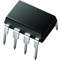
PIC12CE674-04E/P Microchip Technology, PIC12CE674-04E/P Datasheet - Page 600

PIC12CE674-04E/P
Manufacturer Part Number
PIC12CE674-04E/P
Description
IC,MICROCONTROLLER,8-BIT,PIC CPU,CMOS,DIP,8PIN,PLASTIC
Manufacturer
Microchip Technology
Series
PIC® 12Cr
Datasheets
1.PIC16F688T-ISL.pdf
(688 pages)
2.PIC12CE673-10P.pdf
(129 pages)
3.PIC12CE673-10P.pdf
(3 pages)
4.PIC12CE673-10P.pdf
(14 pages)
5.PIC12CE673-10P.pdf
(12 pages)
Specifications of PIC12CE674-04E/P
Rohs Compliant
YES
Core Processor
PIC
Core Size
8-Bit
Speed
4MHz
Peripherals
POR, WDT
Number Of I /o
5
Program Memory Size
3.5KB (2K x 14)
Program Memory Type
OTP
Eeprom Size
16 x 8
Ram Size
128 x 8
Voltage - Supply (vcc/vdd)
3 V ~ 5.5 V
Data Converters
A/D 4x8b
Oscillator Type
Internal
Operating Temperature
-40°C ~ 125°C
Package / Case
8-DIP (0.300", 7.62mm)
Processor Series
PIC12C
Core
PIC
Data Bus Width
8 bit
Data Ram Size
128 B
Maximum Clock Frequency
4 MHz
Number Of Programmable I/os
5
Number Of Timers
8
Maximum Operating Temperature
+ 125 C
Mounting Style
Through Hole
3rd Party Development Tools
52715-96, 52716-328, 52717-734
Development Tools By Supplier
ICE2000
Minimum Operating Temperature
- 40 C
On-chip Adc
8 bit
Lead Free Status / RoHS Status
Lead free / RoHS Compliant
Connectivity
-
Lead Free Status / Rohs Status
Details
Available stocks
Company
Part Number
Manufacturer
Quantity
Price
Company:
Part Number:
PIC12CE674-04E/P
Manufacturer:
MICROCHIP
Quantity:
12 000
- PIC16F688T-ISL PDF datasheet
- PIC12CE673-10P PDF datasheet #2
- PIC12CE673-10P PDF datasheet #3
- PIC12CE673-10P PDF datasheet #4
- PIC12CE673-10P PDF datasheet #5
- Current page: 600 of 688
- Download datasheet (3Mb)
PICmicro MID-RANGE MCU FAMILY
30.21
DS31030A-page 30-30
Param.
No.
SCL
SDA
90
91
92
93
§ This specification ensured by design. For the value required by the I
“Appendix.”
Maximum pin capacitance = 10 pF for all I
Note: Refer to
T
Symbol Characteristic
T
T
T
HD
SU
HD
SU
Example Master SSP I
:
:
:
:
STO
STO
STA
STA
START
condition
Setup time
START
condition
Hold time
STOP condition 100 kHz mode
Setup time
STOP condition 100 kHz mode
Hold time
90
Figure 30-15:
Figure 30-1
Table 30-27:
Condition
START
91
for load conditions.
100 kHz mode
400 kHz mode
1 MHz mode
100 kHz mode
400 kHz mode
1 MHz mode
400 kHz mode
1 MHz mode
400 kHz mode
1 MHz mode
2
Example Master SSP I
C Mode Timing Waveforms and Requirements
Example Master SSP I
2
C pins.
(1)
(1)
(1)
(1)
2(T
2(T
2(T
2(T
2(T
2(T
2(T
2(T
2(T
2(T
2(T
2(T
OSC
OSC
OSC
OSC
OSC
OSC
OSC
OSC
OSC
OSC
OSC
OSC
)(BRG + 1) §
)(BRG + 1) §
)(BRG + 1) §
)(BRG + 1) §
)(BRG + 1) §
)(BRG + 1) §
)(BRG + 1) §
)(BRG + 1) §
)(BRG + 1) §
)(BRG + 1) §
)(BRG + 1) §
)(BRG + 1) §
Min
2
C Bus Start/Stop Bits Requirements
2
C Bus Start/Stop Bits Timing Waveforms
2
C specification, please refer to
Typ Max Units
—
—
—
—
—
—
—
—
—
—
—
—
—
—
—
—
—
—
—
—
—
—
—
—
ns
ns
ns
ns
92
1997 Microchip Technology Inc.
Condition
Only relevant for repeated
START condition
After this period the first
clock pulse is generated
STOP
Figure A-11
93
Conditions
of the
Related parts for PIC12CE674-04E/P
Image
Part Number
Description
Manufacturer
Datasheet
Request
R

Part Number:
Description:
IC MCU OTP 2KX14 A/D&EE 8DIP
Manufacturer:
Microchip Technology
Datasheet:

Part Number:
Description:
IC MCU OTP 2KX14 A/D&EE 8DIP
Manufacturer:
Microchip Technology
Datasheet:

Part Number:
Description:
IC MCU OTP 2KX14 A/D&EE 8DIP
Manufacturer:
Microchip Technology
Datasheet:

Part Number:
Description:
IC MCU EPROM 2KX14 A/D&EE 8CDIP
Manufacturer:
Microchip Technology
Datasheet:

Part Number:
Description:
IC MCU OTP 2KX14 A/D&EE 8DIP
Manufacturer:
Microchip Technology
Datasheet:

Part Number:
Description:
IC MCU OTP 2KX14 A/D&EE 8DIP
Manufacturer:
Microchip Technology
Datasheet:

Part Number:
Description:
8-Pin/ 8-Bit CMOS Microcontroller with A/D Converter and EEPROM Data Memory
Manufacturer:
Microchip Technology
Datasheet:

Part Number:
Description:
Manufacturer:
Microchip Technology Inc.
Datasheet:

Part Number:
Description:
Manufacturer:
Microchip Technology Inc.
Datasheet:

Part Number:
Description:
Manufacturer:
Microchip Technology Inc.
Datasheet:

Part Number:
Description:
Manufacturer:
Microchip Technology Inc.
Datasheet:

Part Number:
Description:
Manufacturer:
Microchip Technology Inc.
Datasheet:


