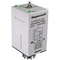
712XBXC-120V Magnecraft / Schneider Electric, 712XBXC-120V Datasheet - Page 5

712XBXC-120V
Manufacturer Part Number
712XBXC-120V
Description
ALTERNATING LOAD RELAY, DPDT, 12A
Manufacturer
Magnecraft / Schneider Electric
Datasheet
1.712XAXC-120V.pdf
(6 pages)
Specifications of 712XBXC-120V
Contact Current Max
12A
Contact Voltage Ac Nom
240V
Contact Voltage Dc Nom
30V
Contact Configuration
DPDT
Relay Mounting
Plug In
Average Power Consumption
1.8VA
External Height
65mm
Lead Free Status / RoHS Status
Lead free / RoHS Compliant
4
1
S1
7/10
712XAXC
5
Wiring Diagram:
712XAXC
8 Pin Octal, with an SPDT
Contact Configuration.
If the Top Toggle Switch is in “Alternate” position closing Switch S1 will alternate the loads between LA and LB.
If the Top Toggle Switch is in “Lock 1” position Load LA is ON and Load LB is OFF. Switch S1 is not used in this mode.
If the Top Toggle Switch is in “Lock 2” position Load LA is OFF and Load LB is ON. Switch S1 is not used in this mode.
Wiring Diagram:
712XBXC (DUPLEX)
8 Pin Octal, with a DPDT
Contact Configuration.
Duplex Capabilities.
If the Top Toggle Switch is in “Alternate” position closing Switch S1 will alternate the loads between LA and LB while switch
S2 will only control LA.
If the Top Toggle Switch is in “Lock 1” position Switch S1 will control LA while switch S2 will control LB.
If the Top Toggle Switch is in “Lock 2” position Switch S1 will control LB while switch S2 will control LA.
Duplex (Cross Wired) Functionality: This model operates the same as alternating relays except when both the control
Switches S1 and S2 are closed, Load A and Load B energize simultaneously. The DPDT 8-pin, cross wired option, allows
extra system load capacity through simultaneous operation of both motors when needed. Relay contacts are not isolated.
+
Theory of Operation
V
–
3
8
2
LB
LA
2) 8 PIN OCTAL DPDT CROSSWIRED
•3-5 INTERNALLY JUMPERED
S2
S1
1) 8 PIN OCTAL SPDT
V is Input Voltage
LA is Load #1
LB is Load #2
S1 is Control Switch #1
S2 is Control Switch #2
2
1
4
1
S1
3
V is Input Voltage
LA is Load #1
LB is Load #2
S1 is Control Switch #1
712XBXC
712XAXC
5
5
+
+
V
6
V
–
7
8
–
3
8
2
LB
LA
WIRING DIAGRAMS
LB
LA
A.
B.
2) 8 PIN OCTAL DPDT CROSSWIRED
•3-5 INTERNALLY JUMPERED
S2
S1
3) 11 PIN OCTAL DPDT (K)
•PIN 9 NORMALLY OPEN
•PIN 10 COMMON
•PIN 11 NORMALLY CLOSED
2
1
4
10
2
S1
3
712XBXCK
712XBXC
6
+
5
+
V
V
11
–
9
6
8
1
3
–
7
8
LA
LB
LB
LA
M agne cr aft S olu tion Guide 1 0 5 A
4) 11 PIN OCTA
3) 11 PIN OCTA
•PIN 9 NORMA
•PIN 10 COMM
•PIN 11 NORM
•PIN 9 NORM
•PIN 10 COM
•PIN 11 NOR
4
10
2
4
10
2
S1
712XBX
S1
712XBX
6
6
+
+
V
V


