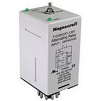
712XBXC-120V Magnecraft / Schneider Electric, 712XBXC-120V Datasheet - Page 6

712XBXC-120V
Manufacturer Part Number
712XBXC-120V
Description
ALTERNATING LOAD RELAY, DPDT, 12A
Manufacturer
Magnecraft / Schneider Electric
Datasheet
1.712XAXC-120V.pdf
(6 pages)
Specifications of 712XBXC-120V
Contact Current Max
12A
Contact Voltage Ac Nom
240V
Contact Voltage Dc Nom
30V
Contact Configuration
DPDT
Relay Mounting
Plug In
Average Power Consumption
1.8VA
External Height
65mm
Lead Free Status / RoHS Status
Lead free / RoHS Compliant
D
2) 8 PIN OCTAL DPDT CROSSWIRED
•3-5 INTERNALLY JUMPERED
S2
S1
3) 11 PIN OCTAL DPDT (K)
•PIN 9 NORMALLY OPEN
•PIN 10 COMMON
•PIN 11 NORMALLY CLOSED
M ag n e cr a f t S olu t i o n G ui de 10 5A
2
1
4
10
2
S1
3
712XBXC
712XBXCK
6
5
+
+
Wiring Diagram:
712XBXCK
11 Pin Octal with a DPDT
Contact Configuration.
Pin 9 is Normally Open
and Pin 11 is Normally
Closed.
If the Top Toggle Switch is in “Alternate” position closing Switch S1 will alternate the loads between LA and LB.
If the Top Toggle Switch is in “Lock 1” position Load LA is ON and Load LB is OFF. Switch S1 is not used in this mode.
If the Top Toggle Switch is in “Lock 2” position Load LA is OFF and Load LB is ON. Switch S1 is not used in this mode.
Wiring Diagram:
712XBXCK1
11 Pin Octal with a DPDT
Contact Configuration.
Pin 9 is Normally Closed
and Pin 11 is Normally
Open.
If the Top Toggle Switch is in “Alternate” position closing Switch S1 will alternate the loads between LA and LB.
If the Top Toggle Switch is in “Lock 1” position Load LA is ON and Load LB is OFF. Switch S1 is not used in this mode.
If the Top Toggle Switch is in “Lock 2” position Load LA is OFF and Load LB is ON. Switch S1 is not used in this mode.
Note: Input voltage must be applied at all times for proper alternation. The use of a solid state control switch for S1 or S2
may not initiate alternation correctly. S1 or S2 voltage must be from the same supply as the unit’s input voltage (see wiring
diagrams). Loss of input voltage resets the unit; Load A becomes the lead load for the next operation.
V
V
11
6
–
9
–
8
1
3
7
8
LA
LB
LB
LA
4) 11 PIN OCTAL DPDT (K1)
3) 11 PIN OCTAL DPDT (K)
•PIN 9 NORMALLY CLOSED
•PIN 10 COMMON
•PIN 11 NORMALLY OPEN
•PIN 9 NORMALLY OPEN
•PIN 10 COMMON
•PIN 11 NORMALLY CLOSED
V is Input Voltage
LA is Load #1
LB is Load #2
S1 is Control Switch #1
V is Input Voltage
LA is Load #1
LB is Load #2
S1 is Control Switch #1
4
10
2
S1
4
10
2
S1
712XBXCK1
712XBXCK
6
6
+
+
V
V
11
–
11
9
–
8
1
3
9
8
1
3
LA
LB
LA
LB
C.
D.
4) 11 PIN OCTAL DPDT (K1)
•PIN 9 NORMALLY CLOSED
•PIN 10 COMMON
•PIN 11 NORMALLY OPEN
4
10
2
S1
712XBXCK1
6
+
V
11
–
9
8
1
3
LA
LB
7/11


