61-3440.4/2 EAO, 61-3440.4/2 Datasheet - Page 32
61-3440.4/2
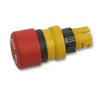
Manufacturer Part Number
61-3440.4/2
Description
SWITCH, EMERGENCY STOP
Manufacturer
EAO
Datasheet
1.61-3440.42.pdf
(48 pages)
Specifications of 61-3440.4/2
Mounting Hole Dia
16mm
Svhc
No SVHC (18-Jun-2010)
Approval Bodies
VDE, UL, CSA, SEV
Behind Panel Depth
43mm
Ip/nema Rating
IP65
Panel Cutout
RoHS Compliant
For Use With
61 Series Illuminated Pushbutton Switches


Technical Data
rules
approvals
switching system
material
mechanical characteristics
actuator with slow-make switching element
IEC 1058 EN 61 058
- SEV 250 VAC/6 A
- CSA 300 VAC
- UR 250 VAC/6 A
- VDE 250 VAC/6 A
- German Lloyd
Self-cleaning, double-break, snap-action switching elements (con-
tact gap 2 x 1.5 mm).
The elements can be supplied with the following choice of switching
functions:
for illuminated pushbutton or switch actuator with 2 positions:
max. 2 normally open contacts, max. 2 normally closed contacts or
combined
for switch actuator with 3 positions:
max. 2 normally open contacts, max.2 normally closed contacts or
combined
The switching element can be easily snapped to or dismantled from
the actuator.
actuator case
polyetherimide PEI, self-extinguishing
front bezel
polyetherimide PEI and chromium plated
front ring
of aluminium
lenses
polymethylmethacrylat PMMA, polycarbonate PC, aluminium
(mushroom head cap: polyamide PA)
material of contacts
gold (low level), silver
switching element
polyamide PA, polysulfone PSU
actuating force
measured at the lens of the illuminated pushbutton:
3.5-20 N, depending on the number of switching elements
measured at the mushroom head cap of the emergency stop
switch:
max. 65 N
actuating torque
measured at the lever or key of the selector-or keylock switch:
4-16 Ncm, depending on the number of switching elements
emergency stop switch: 15 Ncm
138
01.2000
electrical characteristics
actuating travel
illuminated pushbutton :3 mm
emergency stop switch:10 mm
switch actuator with 2 positions:
switch actuator with 3 positions:
ambient air temperature
-25°C to +55°C
for indicators and illuminated pushbuttons mounted as a block ,
make sure the heat can escape freely
(as per DIN IEC 68-)
connection method
universal terminal (soldering-/plug-in terminal):
max. wire diameter: 2 of 1 mm
max. wire cross-section of stranded cable: 1 x 0.75 mm
soldering-/plug-in terminal: 2.8 x 0.5 mm
screw terminal:
max. wire cross-section of stranded cable: 1 x 1 mm
degree of polution
3
degree of protection
indicator, illuminated pushbutton, emercency stop switch, selector-
and keylock switch: front IP 65
switching element IP 40
screw terminal IP 20 as per VDE 0106 Teil 100
mechanical life
as per IEC 512-5-6
momentary action 2 mio. cycles of operation
maintained action 1 mio. cycles of operation
keylock switch 50000 cycles of operation
selector switch 100000 cycles of operation
emergency stop switch 50000 cycles of operation
rebound time
<= 2 ms
resistance to shock
(single impacts, semi-sinusoidal)
50 g, 11 ms as per IEC 512-4-3, IEC 68-2-27
resistance to vibration
(sinusoidal)
10 g, at 10- 2000- 10 Hz, amplitude 0.75 mm as per IEC 512-4-4,
IEC 68-2-6
storage temperature
-40°C to + 85°C
(as per DIN IEC 68-)
continuous thermal current lth
universal terminal 5 A
screw terminal 10 A
The maximum current in continuous operation and at ambient tem-
perature not exceeding the quoted maximum values.
electric strength
as per VDE 0630 (IEC 512-2-11)
4000 VAC, 50 Hz, 1 between all terminals and earth
electrical life
switching element of emergency stop switch 6´050 cycles of oper-
ation
1 x ca. 42° deflection momentary action
1 x ca. 90° deflection maintained action
2 x ca. 42° deflection momentary action
2 x ca. 90° deflection maintained action
2
2
2
61
Related parts for 61-3440.4/2
Image
Part Number
Description
Manufacturer
Datasheet
Request
R

Part Number:
Description:
LAMP, INDICATOR, INCAND, T-1 3/4
Manufacturer:
EAO
Datasheet:

Part Number:
Description:
LAMP, IND, INCAND, T-1 3/4, RED
Manufacturer:
EAO
Datasheet:

Part Number:
Description:
LAMP, IND, INCAND, T-1 3/4, RED
Manufacturer:
EAO
Datasheet:

Part Number:
Description:
Switching Element, Pushbutton; 1; 3 Normally Open; Snap-Mount; Gold/Silver; 5 A
Manufacturer:
EAO Switch
Datasheet:
Part Number:
Description:
Switching Element, Pushbutton; 1; 3 Normally Open; Snap-Mount; Silver; 250 VAC
Manufacturer:
EAO Switch
Datasheet:
Part Number:
Description:
Switching Element, Pushbutton; 1; 3 Normally Closed; Snap-Mount; Gold/Silver
Manufacturer:
EAO Switch
Datasheet:
Part Number:
Description:
CONN JACK 6P FLNG K3 COMPU-SHLD
Manufacturer:
Stewart Connector
Datasheet:

Part Number:
Description:
SWITCHING ELEMENT 2NO/1NC 6A, SOLDER LUG
Manufacturer:
EAO
Datasheet:


Part Number:
Description:
ER 3C 3#16S PIN RECP BOX
Manufacturer:
Amphenol Industrial Operations

Part Number:
Description:
IC SWIT PWM CM OVP UVLO HV TO220
Manufacturer:
Fairchild Semiconductor
Datasheet:

Part Number:
Description:
Discrete Semiconductor Modules 1600V 120A DUAL
Manufacturer:
Infineon Technologies

Part Number:
Description:
IC SWIT PWM CM OVP UVLO HV TO220
Manufacturer:
Fairchild Semiconductor
Datasheet:
Part Number:
Description:
IC SWIT PWM CM OVP UVLO HV TO220
Manufacturer:
Fairchild Semiconductor
Datasheet:
