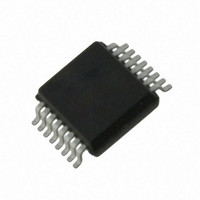
AS5043-ASST austriamicrosystems, AS5043-ASST Datasheet - Page 22

AS5043-ASST
Manufacturer Part Number
AS5043-ASST
Description
IC ENCODER PROG 10-BIT 16-SSOP
Manufacturer
austriamicrosystems
Type
Linear, Rotary Encoder - Programmabler
Datasheet
1.AS5043_PB.pdf
(36 pages)
Specifications of AS5043-ASST
Sensing Range
45mT ~ 75mT
Voltage - Supply
3 V ~ 3.6 V, 4.5 V ~ 5.5 V
Current - Supply
21mA
Current - Output (max)
4mA
Output Type
Analog, Digital
Features
Programmable
Operating Temperature
-40°C ~ 125°C
Package / Case
16-SSOP
Lead Free Status / RoHS Status
Lead free / RoHS Compliant
Other names
AS5043-ASSTTR
AS5043
Data Sheet – Simulation Modelling
16 Simulation Modelling
Figure 21: Arrangement of Hall Sensor Array on Chip (principle)
With reference to Figure 21, a diametrically magnetized permanent magnet is placed above or below the surface of the
AS5043. The chip uses an array of Hall sensors to sample the vertical vector of a magnetic field distributed across the
device package surface. The area of magnetic sensitivity is a circular locus of 1.1mm radius with respect to the center of
the die. The Hall sensors in the area of magnetic sensitivity are grouped and configured such that orthogonally related
components of the magnetic fields are sampled differentially.
orthogonally related cosine vector of the magnetic field.
The angular displacement (Θ) of the magnetic source with reference to the Hall sensor array may then be modelled by:
The ±0.5° angular error assumes a magnet optimally aligned over the center of the die and is a result of gain mismatch
errors of the AS5043. Placement tolerances of the die within the package are ±0.235mm in X and Y direction, using a
reference point of the edge of pin #1 (Figure 21).
In order to neglect the influence of external disturbing magnetic fields, a robust differential sampling and ratiometric
calculation algorithm has been implemented. The differential sampling of the sine and cosine vectors removes any
common mode error due to DC components introduced by the magnetic source itself or external disturbing magnetic
fields. A ratiometric division of the sine and cosine vectors removes the need for an accurate absolute magnitude of the
magnetic field and thus accurate Z-axis alignment of the magnetic source.
The recommended differential input range of the magnetic field strength (B
die. In addition to this range, an additional offset of ±5mT, caused by unwanted external stray fields is allowed.
The chip will continue to operate, but with degraded output linearity, if the signal field strength is outside the
recommended range. Too strong magnetic fields will introduce errors due to saturation effects in the internal
preamplifiers. Too weak magnetic fields will introduce errors due to noise becoming more dominant.
www.austriamicrosystems.com
The differential signal Y1-Y2 will give a sine vector of the magnetic field. The differential signal X1-X2 will give an
Θ
=
arctan
(
(
X
Y
1
1
−
−
Y
X
2
2
)
)
±
0
5 .
°
Revision 1.80
(X1-X2)
,B
(Y1-Y2)
) is ±75mT at the surface of the
22 – 36


