D10INFP BANNER ENGINEERING, D10INFP Datasheet - Page 6
D10INFP
Manufacturer Part Number
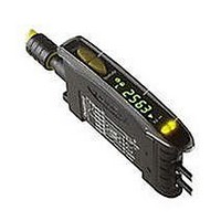
D10INFP
Description
Photoelectric Sensor
Manufacturer
BANNER ENGINEERING
Type
Analog And Discrete Outputr
Datasheet
1.D10INFP.pdf
(16 pages)
Specifications of D10INFP
Sensor Output
NPN
Contact Current Max
150mA
Switch Terminals
Connector
Peak Reflow Compatible (260 C)
No
Sensor Input
Fiber Optic
Output Type
Transistor
Leaded Process Compatible
No
Fiber Optic Sensor Type
Analog And Discrete Output


• Two-point TEACH to set a single threshold.
• Threshold is adjustable using the “+” and “–” buttons (see Manual Adjust, page 8).
D10 Expert
6
P/N 65448 rev. E
• Press and
• Present Output
• Click Static button.
• Present Output
• Click Static button.
hold Static (-)
button.
ON target.
OFF target.
Push Button
™
Analog and Discrete Outputs
T
T
T
T
• No action required;
• Present Output ON
• Single-pulse the
• Present Output OFF
• Single-pulse the
T
T
sensor is automatically
ready for 1st TEACH condition.
target.
remote line.
target.
remote line.
T
T
T
T
0.04 sec. ≤ T ≤ 0.8 sec.
T
T
Remote
Static TEACH
T
T
T
T
T
T
T
T
• Display flashes “1st”
• Arrow icon turns red
• Display flashes “2nd”
TEACH conditions acceptable:
• Display flashes “pass,” followed
• Sensor returns to RUN mode with
• Arrow icon turns green
TEACH conditions unacceptable:
• Display flashes “fail” and
• Arrow icon remains red
• After 60 seconds, sensor returns
by a number (denoting contrast);
see table below.
new settings.
returns to “1st”
to RUN mode (Arrow icon
turns green) without changing
settings.
500+
100 - 500
32 - 99
0 - 31
Contrast Values
Banner Engineering Corp.
www.bannerengineering.com • Tel: 763.544.3164
Excellent
Good
Low
Marginal
Result
•
Minneapolis, MN U.S.A.
Related parts for D10INFP
Image
Part Number
Description
Manufacturer
Datasheet
Request
R

Part Number:
Description:
Photoelectric Sensor
Manufacturer:
BANNER ENGINEERING
Datasheet:

Part Number:
Description:
Photoelectric Sensor
Manufacturer:
BANNER ENGINEERING
Datasheet:

Part Number:
Description:
LEDIR70XD4-XM-81039 MAX INTENS STROBE ONLY NO BANNER MARKS
Manufacturer:
BANNER ENGINEERING
Part Number:
Description:
M18SP6DL-72225 LABELED MOELLER NO BANNER MARKINGS BULK PACK
Manufacturer:
BANNER ENGINEERING
Part Number:
Description:
M18SP6DLQ-72226 LABLED MOELLER NO BANNER MARKINGS BULK PACK
Manufacturer:
BANNER ENGINEERING
Part Number:
Description:
M18SP6L-72223 LABELED MOELLER NO BANNER MARKINGS BULK PACK
Manufacturer:
BANNER ENGINEERING
Part Number:
Description:
M18SP6LQ-72224 LABELED MOELLER NO BANNER MARKINGS BULK PACK
Manufacturer:
BANNER ENGINEERING
Part Number:
Description:
P4D1-77908 P4 DRIVER GENERIC NO BANNER MARKINGS RESALE TO CUSTOMER
Manufacturer:
BANNER ENGINEERING
Part Number:
Description:
Photoelectric Sensor
Manufacturer:
BANNER ENGINEERING
Datasheet:

Part Number:
Description:
Programmable Indicator Light
Manufacturer:
BANNER ENGINEERING
Datasheet:
Part Number:
Description:
INDICATOR LED PANEL 50MM GRN/RED/YEL 30V
Manufacturer:
BANNER ENGINEERING
Datasheet:
Part Number:
Description:
Programmable Indicator Light
Manufacturer:
BANNER ENGINEERING
Datasheet: