E3XNA41F2M Omron, E3XNA41F2M Datasheet - Page 14
E3XNA41F2M
Manufacturer Part Number
E3XNA41F2M
Description
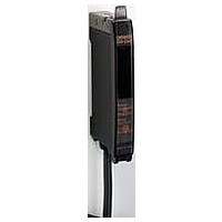
Photoelectric Sensor
Manufacturer
Omron
Type
High Speed Fiber Optic Sensorr
Datasheet
1.E3XNA11F2M.pdf
(28 pages)
Specifications of E3XNA41F2M
Sensor Output
PNP
Sensor Input
Fiber Optic
Output Type
PNP LO/DO
Supply Voltage Max
24V
Switch Terminals
Cable
Supply Voltage Min
12V
Fiber Optic Sensor Type
High Speed Fiber Optic Sensor
Rohs Compliant
Yes
Lead Free Status / RoHS Status
Lead free / RoHS Compliant


E3X-NA
I
Tightening Force
The tightening force applied to the Fiber Unit should be as shown
below.
Use a proper-sized wrench.
Fiber Connection and Disconnection
The E3X-NA Amplifier Unit has a lock button. Connect or discon-
nect the fibers to or from the E3X-NA Amplifier Unit using the
following procedures:
1.
2. Disconnection
Screw-Mounting Model
14
Fiber Units
M3/M4 screw
M6 screw/
6-mm dia. cylinder
1.5-mm dia.
cylinder
2-mm dia./3-mm dia.
cylinder
E32-T12F 5-mm dia.
Teflon model
E32-D12F 6-mm dia.
Teflon model
E32-T16
E32-R21
E32-M21
E32-L25A
E32-T16P
E32-T16PR
E32-T24S
E32-L24L
E32-L25L
E32-T16J
E32-T16JR
E32-T16W
E32-T16WR
Lock button
Nuts
(attachment)
Mounting the Fiber Unit
Open the protective cover, insert the fibers according to the
fiber insertion marks on the side of the Amplifier Unit, and
lower the lock button.
Remove the protective cover and raise the lock button to pull
out the fiber.
Connection
Fiber
Spring mounting clip
Toothed washers
Fiber insertion
mark
Clamping torque
0.78 N·m max.
0.98 N·m max.
0.2 N·m max.
0.29 N·m max.
0.78 N·m max.
0.49 N·m max.
0.59 N·m max.
Up to 5 mm to the tip: 0.49 N·m max.
More than 5 mm from the tip: 0.78 N·m max.
0.78 N·m max.
0.29 N·m max.
0.3 N·m max.
10.7 mm
Insertion position
Cylindrical Model
Retaining screw
(flat head or sunken head)
(M3 max.)
Note:
3. Precautions for Fiber Connection/Disconnection
Cutting Fiber
Insert a fiber into the Fiber Cutter and determine the length of the
fiber to be cut.
Press down the Fiber Cutter in a single stroke to cut the fiber.
The cutting holes cannot be used twice. If the same hole is used
twice, the cutting face of the fiber will be rough and the sensing
distance will be reduced. Always use an unused hole.
Cut a thin fiber as follows:
1. An attachment is temporarily fitted to a thin fiber before ship-
2. Secure the attachment after adjusting the position of it in the
3. Insert the fiber to be cut into the E39-F4.
4. Finished state (proper cutting state)
Note:
Be sure to lock or unlock the lock button within an ambient
temperature range between −10°C and 40°C.
ment.
direction indicated by the arrow.
To maintain the fiber properties, confirm that the lock is re-
leased before removing the fiber.
Insert the fiber in the direction indicated by the arrow.
Locked
Three holes for
standard fiber
(2.2-mm dia.)
Approx.
0.5 mm
Temporarily fitted
Unlocked
Thin fiber attachment (E39-F9)
Insertion direction
Two holes for
thin fiber
Cutter
(E39-F4)
Protective cover
E3X-NA
Related parts for E3XNA41F2M
Image
Part Number
Description
Manufacturer
Datasheet
Request
R

Part Number:
Description:
PNP GEN PURPOSE FO AMP
Manufacturer:
Omron
Datasheet:

Part Number:
Description:
G6S-2GLow Signal Relay
Manufacturer:
Omron Corporation
Datasheet:
Part Number:
Description:
Compact, Low-cost, SSR Switching 5 to 20 A
Manufacturer:
Omron Corporation
Datasheet:
Part Number:
Description:
Manufacturer:
Omron Corporation
Datasheet:
Part Number:
Description:
Manufacturer:
Omron Corporation
Datasheet:
Part Number:
Description:
Manufacturer:
Omron Corporation
Datasheet:
Part Number:
Description:
Manufacturer:
Omron Corporation
Datasheet:
Part Number:
Description:
Manufacturer:
Omron Corporation
Datasheet:
Part Number:
Description:
Manufacturer:
Omron Corporation
Datasheet: