Printed in USA
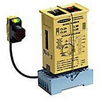
MAXI-AMP
Logic-level Input Modules
Banner CL Series MAXI-AMP™ modules are the perfect solution
for many sensing/control applications where economy, versatility,
dependability, and ruggedness are important. CL Series MAXI-AMPs
combine power supply, timing logic (in CL5 models) and output relay
in a single compact, cost-saving module. The integrated, stand-alone
design saves both the expense of a separate control chassis and a sub-
stantial amount of panel space. Several models are available, for either
120V ac or 240V ac operation, and either with or without timing logic
(models are listed in table at above right). Alternatively, any model
may be powered by 12 to 28V dc.
The well-defined electrical characteristics of CL Series MAXI-AMP
modules provide a wealth of application possibilities. The input cir-
cuit accepts signals from any Banner dc sensor with an NPN (current
sinking) output; as well as from MAXI-AMP, MICRO-AMP, and
Plug Logic modules. The input is compatible with almost any sensor
or circuit which has an NPN transistor (current sinking) output. Ad-
ditionally, inputs may be generated by limit switches, contact closures,
and optical couplers. A 50mA power supply is included for powering
10 to 30V dc devices.
CL5 models offer a versatile multi-function timing logic circuit which is
programmable for twelve of the most popular and useful delay, one-shot,
and latch functions (see page 5). The MAXI-AMP offers the choice of
either single or dual timing functions in the same module. Logic and
timing may be easily reprogrammed as control requirements change.
Solid-state Output Option
CL Series modules are available with a solid-state relay which replaces
the electromechanical relay. This is actually two SPST solid-state
contacts. One contact will switch ac loads, and is rated at 250V ac
maximum and 3/4 amps maximum at 25 degrees C (derated to 1/2 amp
at 50 degrees C). A solid-state contact is particularly helpful when
switching inductive ac loads which can cause electrical "noise" and
contact damage when switched with a "hard" relay contact.
The other solid-state contact will switch dc loads of up to 30V dc and
up to 50 milliamps. Both solid-state outputs are electrically isolated
from the MAXI-AMP power supply. Both outputs switch within the 1
millisecond response time of the CL module circuitry. NOTE: ac loads
may take up to 1/2 cycle (8.3 milliseconds) to turn "off".
Both outputs are normally open, but may be programmed for normally
closed operation.
Except for the output configuration, the specifications for the models
listed in the table at the right are exactly the same as for the standard
CL Series models.
Recognized
Please read Personnel Safety Warning, page
3.
Certified
™
CL Series
In order to allow accurate timing adjustments, each CL5 model has
three time ranges to choose from. Timing adjustments are made via
rugged 15-turn potentiometers. Circuitry is included to prevent any
possibility of false output on power-up.
An auxiliary input is available on CL5 models for interrogation or
reset of the selected logic function by using an additional sensor or
input signal (see example, page 3). Page 5 describes the function of
the auxiliary input for each logic mode.
The output circuit for all CL Series modules is an SPDT 5-amp elec-
tro-mechanical relay. A solid-state relay is offered as an option to the
electromechanical relay (see information below).
Additionally, CL3 models have an NPN transistor solid-state switch.
This solid-state output may be used to take advantage of the amplifier's
fast 1-millisecond response. This output may be connected directly to
the primary or auxiliary input of other Banner logic modules, including
CL5 modules, MICRO-AMP logic modules, and Plug Logic modules.
In addition, this output can interface to other dc devices or circuits
such as counters, rate meters, or programmable controllers. Switching
capacity is 20mA at 12V dc. The output may be programmed for either
normally open or normally closed operation.
Like all MAXI-AMPs, the CL Series modules are designed both
electrically and mechanically for solid dependability in industrial
environments.
CL3RA
CL3RB
CL5RA
CL5RB
MODEL
MODEL
CL3A
CL3B
CL5A
CL5B
105 to 130V ac, or
12 to 28V dc
210 to 250V ac, or
12 to 28V dc
105 to 130V ac, or
12 to 28V dc
210 to 250V ac, or
12 to 28V dc
105 to 130V ac, or
12 to 28V dc
210 to 250V ac, or
12 to 28V dc
105 to 130V ac, or
12 to 28V dc
SUPPLY
VOLTAGE
SUPPLY
VOLTAGE
210 to 250V ac, or
12 to 28V dc
SPST solid-
state contact for
switching AC
loads up to 250V
ac and up to 3/4
amp, plus solid-
state contact for
switching dc
loads up to 30V
dc and up to
50mA.
SPDT electro-
mechanical
relay, plus NPN
transistor solid-
state switch
SPDT electro-
mechanical relay
(5 amp contact
rating)
OUTPUT
OUTPUT
LOGIC
LOGIC
P/N 03449D4E
12
timing func-
tions
12
timing func-
tions
ON/OFF
ON/OFF