CL5RA BANNER ENGINEERING, CL5RA Datasheet - Page 3
CL5RA
Manufacturer Part Number
CL5RA
Description
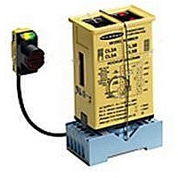
Logic Module
Manufacturer
BANNER ENGINEERING
Datasheet
1.CL5RA.pdf
(6 pages)
Specifications of CL5RA
Leaded Process Compatible
No
Peak Reflow Compatible (260 C)
No
Ssr Output Type
SPDT Electromechanical
Signal Input Type
Voltage, Current
No. Of Analog Outputs
1
Supply Voltage Max
130VAC
Load Current Ac
4A
Switch Terminals
Pin Connector / Plug-in Socket
Load Current Dc
60mA
Supply Voltage Min
105VAC
Operating Voltage Max
28VDC
Contact Configuration
SPDT
Count Input Frequency
60Hz
No. Of Analog Inputs
1
Lead Free Status / Rohs Status
RoHS Exempt Product


3
Sensor Hookup Diagrams, CL Series MAXI-AMP Modules
To MAXI-BEAM Sensors
Use of Auxiliary Input (CL5 models)
CL5 model MAXI-AMPs have an auxiliary input at terminal #9 which may
be used for the interrogation or reset of the selected logic function. This is
accomplished by a switch closure between pins #9 and #1 (Common). The
auxiliary input may also be switched by a DC device with an NPN transistor
(current sinking) output. The effect of the auxiliary input is described for
each logic function on page 5.
This example shows a typical inspection/rejection scheme which uses a
Banner MINI-BEAM as the inspection sensor. Typically, the CL5 module
would be programmed for the ONE-SHOT or DELAYED ONE-SHOT logic
function. If the SM312 "sees" an acceptable condition when the SE612 senses
the leading (or trailing) edge of the product, the SM312 will inhibit a reject
pulse from occuring. Reject products will be ejected by the output pulse.
NOTE: the MAXI-AMP can supply 50mA for external 10 to 30V dc devices.
Carefully check the current draw of the devices to be powered by the MAXI-AMP.
To ECONO-BEAM SE612
Series Sensors
To MINI-BEAM SM312 Series Sensors
Only MACHINE-GUARD and PERIMETER-GUARD Systems, and other systems so designated, are designed to meet OSHA and ANSI machine safety
standards for point-of-operation guarding devices. No other Banner sensors or controls are designed to meet these standards, and they must NOT be used
as sensing devices for personnel protection.
NOTE: use power block model RPBT.
4
5
6
7
8
6
7
8
4
5
6
7
8
4
5
NOTE: Black wire is not used
model
CL3�
CL5�
or �
model
model
CL3�
CL5�
CL3�
CL5�
WARNING
sary to allow their use in personnel safety applications. A failure or malfunction can result in either an energized or a de-energized
output condition.
Never use these products for personnel protection. Their use as safety devices may create an unsafe condition which could lead to seri-
ous injury or death.
or �
or �
NOTE: black wire is not used.
11
10
3
2
1
9
11
10
3
2
1
9
11
10
NOTE: Black wire is not used
3
2
1
9
MAXI-BEAM
BROWN
WHITE
BLUE
The MAXI-AMP modules described in this data sheet do NOT include the self-checking redundant circuitry neces-
BLUE
SE612
WHITE
BROWN
SM312
RPBT
4�
3�
2�
1
This hookup is for DC NPN (current sinking) models of S18 Series, Q25 Series, and
other DC sensors bearing the EZ-BEAM logo.
To VALU-BEAM SM912 Series
Sensors
To MULTI-BEAM Sensors
To EZ-BEAM Sensors
NOTE: use power block model
PBT or PBT2.
NOTE: the MAXI-AMP cannot power a MULTI-BEAM emitter and receiver pair.
Use a separate power source for the emitter (e.g.- power block PBA-1, etc.)
NOTE: White wire is not used
5
6
7
8
4
6
7
8
4
5
4
5
6
7
8
NOTE: Black wire is not used
model
model
model
CL3�
CL5�
CL3�
CL5�
CL3�
CL5�
or �
or �
or �
11
10
3
2
1
9
10
11
11
10
3
2
1
9
3
2
1
9
MULTI-BEAM
BLUE
SM912
BROWN
BLACK
BLUE
WHITE
BROWN
3
1
PBT
4
2
Related parts for CL5RA
Image
Part Number
Description
Manufacturer
Datasheet
Request
R

Part Number:
Description:
Photoelectric Sensor
Manufacturer:
BANNER ENGINEERING
Datasheet:

Part Number:
Description:
Photoelectric Sensor
Manufacturer:
BANNER ENGINEERING
Datasheet:

Part Number:
Description:
LEDIR70XD4-XM-81039 MAX INTENS STROBE ONLY NO BANNER MARKS
Manufacturer:
BANNER ENGINEERING
Part Number:
Description:
M18SP6DL-72225 LABELED MOELLER NO BANNER MARKINGS BULK PACK
Manufacturer:
BANNER ENGINEERING
Part Number:
Description:
M18SP6DLQ-72226 LABLED MOELLER NO BANNER MARKINGS BULK PACK
Manufacturer:
BANNER ENGINEERING
Part Number:
Description:
M18SP6L-72223 LABELED MOELLER NO BANNER MARKINGS BULK PACK
Manufacturer:
BANNER ENGINEERING
Part Number:
Description:
M18SP6LQ-72224 LABELED MOELLER NO BANNER MARKINGS BULK PACK
Manufacturer:
BANNER ENGINEERING
Part Number:
Description:
P4D1-77908 P4 DRIVER GENERIC NO BANNER MARKINGS RESALE TO CUSTOMER
Manufacturer:
BANNER ENGINEERING
Part Number:
Description:
Photoelectric Sensor
Manufacturer:
BANNER ENGINEERING
Datasheet:

Part Number:
Description:
Programmable Indicator Light
Manufacturer:
BANNER ENGINEERING
Datasheet:
Part Number:
Description:
INDICATOR LED PANEL 50MM GRN/RED/YEL 30V
Manufacturer:
BANNER ENGINEERING
Datasheet:
Part Number:
Description:
Programmable Indicator Light
Manufacturer:
BANNER ENGINEERING
Datasheet: