LQ104V1DG61 Sharp Microelectronics, LQ104V1DG61 Datasheet
LQ104V1DG61
Specifications of LQ104V1DG61
Available stocks


Related parts for LQ104V1DG61


LQ104V1DG61 Summary of contents
Page 1
... P S RODUCT PECIFICATIONS LQ104V1DG61 TFT-LCD Module Spec. Issue Date: April 3, 2006 AVC Liquid Crystal Displays Group No: LD-18316A ...
Page 2
...
Page 3
...
Page 4
... Application This specification applies to color TFT-LCD module, LQ104V1DG61 These specification sheets are the proprietary product of SHARP CORPORATION(”SHARP) and include materials protected under copyright of SHARP. Do not reproduce or cause any third party to reproduce them in any form or by any means, electronic or mechanical, for any purpose, in whole or in part, without the express written permission of SHARP ...
Page 5
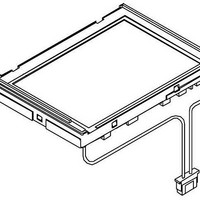
Outline specification. Parameter Display size Active area Pixel format Number of colors (Number of gray scale level) Pixel pitch Pixel configuration Display mode Unit outline dimensions *1 Mass Surface treatment *1: excluding backlight cables. Outline dimensions is shown in ...
Page 6
Input Terminals 4-1. TFT-LCD panel driving CN1 Used connector: DF9MA-31P-1V(32 CN1 pin arrangement from module surface Pin No. Symbol 1 GND 2 CK Clock signal for sampling each data signal 3 Hsync Horizontal synchronous signal 4 Vsync ...
Page 7
R/L = High, U/D = Low R/L = High, U/D = High 4-2. Backlight driving CN2 ,CN3 Used connector : BHR-02(8.0)VS-1N (JST) Corresponding connector : SM02(8.0)B-BHS-1-TB or -1N-TB (JST) Pin no. symbol 1 VHIGH Power supply for ...
Page 8
Recommended operation condition Parameter Symbol V Input voltage I Supply voltage V CC Ambient temperature Topa [Note1]CK,R0 R5,G0 G5,B0 B5,Hsync,Vsync,ENAB,R/L,U/D [Note2] Vcc-turn-on conditions 0<t1 15ms 0<t2 10ms 0<t3 100ms 0<t4 1s t5>200ms Vcc-dip conditions 1) 2.5V Vcc td 10ms ...
Page 9
Electrical Characteristics 7-1. TFT-LCD panel driving Parameter Current dissipation Vcc=3.3V Vcc=5.0V Permissive input ripple voltage Input voltage Low Input voltage High Input current 1 Low(VI=0V) Hogh(VI=Vcc) Input current 2 Low(VI=0V) Hogh(VI=Vcc) Input current 3 Low(VI=0V) Hogh(VI=Vcc) [Note1] Typical current ...
Page 10
Backlight driving The backlight system is an edge-lighting type with double CCFT (Cold Cathode Fluorescent Tube). The characteristics of single lamp are shown in the following table. (It is usually required to measure under the following condition. condition:IL=6.0mA,Ta=25 Parameter ...
Page 11
Timing Characteristics of input signals Timing diagrams of input signal are shown in Fig.2. 8-1. Timing characteristics Parameter Clock Frequency High time Low time Duty ratio Data Setup time Hold time Horizontal Cycle sync. signal Pulse width Vertical Cycle ...
Page 12
...
Page 13
Input Signals, Basic Display Colors and Gray Scale of Each Color Colors & Gray scale Gray Scale Black 0 0 Blue ...
Page 14
Optical Characteristics Parameter Symbol Viewing Horizontal 21, angle Vertical range Contrast ratio CRn CRo Response Rise time Decay Chromaticity of white Chromaticity of red Chromaticity of green Chromaticity of blue Luminance of white Y White Uniformity [Note] The measurement ...
Page 15
Definitions of viewing angle range: [Note2] Definition of contrast ratio: The contrast ratio is defined as the following. Contrast Ratio (CR) = [Note3] Definition of response time: The response time is defined as the following figure and shall be ...
Page 16
Precautions a) Be sure to turn off the power supply when inserting or disconnecting the cable sure to design the cabinet so that the module can be installed without any extra stress such as warp or twist. ...
Page 17
Packing form Product countries / Areas Piling number of cartons Package quantity in one carton Carton size Total mass of one carton filled with full modules Packing form is shown 14.Reliability test items No. Test item 1 High temperature ...
Page 18
... Barcode Lot Number Discernment code Production month (1-9X Production year (Last digit of dominical year) 15-2 Packing box Label: LQ104V1DG61 社内品番: Barcode LotNO. : Barcode Quantity: ...
Page 19
...
Page 20
...
Page 21
This publication is the proprietary of SHARP and is copyrighted, with all rights reserved. Under the copyright laws, no part of this publication may be reproduced or transmitted in any form or by any means, electronic or mechanical for any ...
Page 22
... ALL EXPRESS AND IMPLIED WARRANTIES, INCLUDING THE WARRANTIES OF MERCHANTABILITY, FITNESS FOR USE AND FITNESS FOR A PARTICULAR PURPOSE, ARE SPECIFICALLY EXCLUDED event will SHARP be liable any way responsible, for any incidental or consequential economic or property damage. NORTH AMERICA SHARP Microelectronics of the Americas 5700 NW Pacific Rim Blvd. Camas, WA 98607, U.S.A. Phone: (1) 360-834-2500 ...