GP2W0110YP0F Sharp Microelectronics, GP2W0110YP0F Datasheet - Page 7
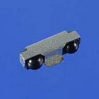
GP2W0110YP0F
Manufacturer Part Number
GP2W0110YP0F
Description
Infrared Transceivers IrDA 115 kbit/s 20 cm Side View
Manufacturer
Sharp Microelectronics
Datasheet
1.GP2W0110YP0F.pdf
(10 pages)
Specifications of GP2W0110YP0F
Wavelength
870 nm
Continual Data Transmission
115.2 Kbit/s
Transmission Distance
20 cm
Radiant Intensity
25 mW/sr
Maximum Rise Time
40 ns, 60 ns
Maximum Fall Time
40 ns, 60 ns
Led Supply Voltage
2 V to 6 V
Operating Voltage
2 V to 3.6 V
Maximum Operating Temperature
+ 85 C
Minimum Operating Temperature
- 25 C
Lead Free Status / RoHS Status
Lead free / RoHS Compliant


10. Mechanical Design Hints
SHARP Electronic Components
Rev. 1.2
ELECTRONIC COMPONENTS
10-1. Recommended Foot Print Recommended Solder Paste screen dimensions
In process section 1, the PCB and SMD
GP2W0110YP0F molded pinout joints are
heated to a temperature of 165
the flux in the solder paste. The temperature
ramp up rate R1 should be within the range of 1
C to 4
must be kept within the temperature range
specified in order to avoid localized temperature
rise in the resin by the infrared lamp.
In process section 2, sufficient time to dry the
solder paste should be provided, a maximum of
120 seconds is recommended for optimum
result. The temperature is recommended to be
stable with little temperature increase,
preferably staying at the level of 165
, March 7, 2002
o
C per second. Package temperature
Heat Up
Solder Paste Dry
Solder Reflow
Cooling
Section
NOTES:
1. Dimensions are in mm.
2. Dimensions are for reference.
3.
0.6
165
o
Temperature
C to activate
200
~165
o
165
C ~ 230
Soldering paste area
o
C.
o
C ~
o
o
C
C
0.475
o
IrDA Low Power Infrared Transceiver
C
o
1.425
Symbol
1.55
2.375
R1
R2
R3
-
3.325
Process section 3 is the section for solder
reflow. In this section, the temperature should
be raised up to the point of 230
at the rate of 1
desired result. The dwell time above 200
must not exceed 60 seconds. Beyond 60
seconds, weak and unreliable connections will
result. The temperature should be then reduced
to at the rate of -1
Please note that deformation of the PCB can
also affect the lead pins of the package, which
may break the gold wire used in the transceiver
module. Full confirmation of the soldering reflow
machine condition is highly recommended for
the optimized result.
Temperature / Time Max.
-1
1
1
o
o
o
GP2W0104YP-5
C ~ 4
C ~ 4
C ~ -4
o
C to 4
o
o
C / sec Max.
C / sec Max.
o
o
C / sec Max.
C to -4
o
C per second (R2) for
o
C per second (R3).
o
C for 5 seconds,
o
7
C
Related parts for GP2W0110YP0F
Image
Part Number
Description
Manufacturer
Datasheet
Request
R

Part Number:
Description:
IC FLASH 32MBIT 110NS 56SSOP
Manufacturer:
Sharp Microelectronics
Datasheet:

Part Number:
Description:
IC FLASH 16MBIT 100NS 56TSOP
Manufacturer:
Sharp Microelectronics
Datasheet:

Part Number:
Description:
IC FLASH 64MBIT 120NS 56TSOP
Manufacturer:
Sharp Microelectronics
Datasheet:

Part Number:
Description:
IC FLASH 16MBIT 90NS 48TSOP
Manufacturer:
Sharp Microelectronics
Datasheet:
Part Number:
Description:
IC SRAM 16KBIT 100NS 24DIP
Manufacturer:
Sharp Microelectronics
Datasheet:
Part Number:
Description:
IC SRAM 16KBIT 100NS 24SOP
Manufacturer:
Sharp Microelectronics
Datasheet:
Part Number:
Description:
IC SRAM 64KBIT 100NS 28DIP
Manufacturer:
Sharp Microelectronics
Datasheet:
Part Number:
Description:
IC SRAM 64KBIT 100NS 28SOP
Manufacturer:
Sharp Microelectronics
Datasheet:
Part Number:
Description:
IC SRAM 64KBIT 100NS 28SOP
Manufacturer:
Sharp Microelectronics
Datasheet:
Part Number:
Description:
IC SRAM 256KBIT 70NS 28DIP
Manufacturer:
Sharp Microelectronics
Datasheet:
Part Number:
Description:
IC FLASH 8MBIT 90NS 48TSOP
Manufacturer:
Sharp Microelectronics
Datasheet:
Part Number:
Description:
IC FLASH 8MBIT 85NS 40TSOP
Manufacturer:
Sharp Microelectronics
Datasheet:
Part Number:
Description:
IC FLASH 8MBIT 85NS 40TSOP
Manufacturer:
Sharp Microelectronics
Datasheet:
Part Number:
Description:
IC FLASH 16MBIT 90NS 48TSOP
Manufacturer:
Sharp Microelectronics
Datasheet:
Part Number:
Description:
IC FLASH 16MBIT 70NS 56TSOP
Manufacturer:
Sharp Microelectronics
Datasheet: