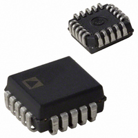
AD7821KPZ Analog Devices Inc, AD7821KPZ Datasheet - Page 12

AD7821KPZ
Manufacturer Part Number
AD7821KPZ
Description
8-BIT ATC CONVERTER IC
Manufacturer
Analog Devices Inc
Datasheet
1.AD7821KRZ-REEL.pdf
(16 pages)
Specifications of AD7821KPZ
Number Of Bits
8
Sampling Rate (per Second)
1M
Data Interface
Parallel
Number Of Converters
3
Power Dissipation (max)
50mW
Voltage Supply Source
Dual ±
Operating Temperature
-40°C ~ 85°C
Mounting Type
Surface Mount
Package / Case
20-LCC (J-Lead)
Lead Free Status / RoHS Status
Lead free / RoHS Compliant
Available stocks
Company
Part Number
Manufacturer
Quantity
Price
Company:
Part Number:
AD7821KPZ
Manufacturer:
Analog Devices Inc
Quantity:
10 000
Company:
Part Number:
AD7821KPZ-REEL
Manufacturer:
Analog Devices Inc
Quantity:
10 000
AD7821
APPLYING THE AD7821
The AD7821 is specified for a unipolar input range of 0 V to +5 V
and a bipolar input range of –2.5 V to +2.5 V. The V
V
below. See the Typical Performance Characteristics section for
operation with unspecified input voltage ranges.
UNIPOLAR OPERATION
Figure 18 gives the configuration and reference voltages required
for 0 V to +5 V operation. The nominal transfer characteristic
for this input range is shown in Figure 19. The output code is
Natural Binary with 1 LSB = (5/256) V = 19.5 mV.
Figure 19. Nominal Transfer Characteristic for Unipolar
(0 V to +5 V) Operation
REF
(+) voltages required for these input ranges are outlined
Figure 18. Unipolar/Bipolar Operation
REF
(–) and
–12–
BIPOLAR OPERATION
Figure 18 gives the configuration and reference voltages required
for –2.5 V to +2.5 V operation. The nominal transfer characteris-
tic for this input range is shown in Figure 20. The output code is
Offset Binary with 1 LSB = ([+2.5 – (–2.5)]/256) V = 19.5 mV.
16-CHANNEL TELECOM A/D CONVERTER
The fast sampling rate (1 MHz) and bipolar operation of the
AD7821 makes it useful in telecom applications for sampling a
number of input channels using a multiplexer. Figure 21 shows
a circuit for such an application.
The maximum signal frequency required for acceptable quality
in telecom applications is 3 kHz. The circuit given in Figure 21
permits each of the 16-input channels to be sampled at a rate of
16 kHz maximum. The sampling rate takes into account such
multiplexer parameters as t
circuit also eases the problem of the antialiasing filter design by
sampling at a rate much greater than that required by the
Nyquist criterion.
Figure 20. Nominal Transfer Characteristic for Bipolar
(–2.5 V to +2.5 V) Operation
ON
, settling time, and so on. The
REV. B


