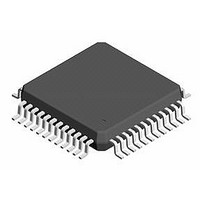
CS4299-JQZR Cirrus Logic Inc, CS4299-JQZR Datasheet - Page 44

CS4299-JQZR
Manufacturer Part Number
CS4299-JQZR
Description
IC AC97 Codec With SRC
Manufacturer
Cirrus Logic Inc
Series
SoundFusion™r
Type
Audio Codec '97r
Datasheet
1.CS4299-JQZ.pdf
(52 pages)
Specifications of CS4299-JQZR
Data Interface
Serial
Resolution (bits)
18 b, 20 b
Number Of Adcs / Dacs
1 / 1
Sigma Delta
Yes
Dynamic Range, Adcs / Dacs (db) Typ
85 / 87
Voltage - Supply, Analog
4.75 V ~ 5.25 V
Voltage - Supply, Digital
3.3 V ~ 5 V
Operating Temperature
0°C ~ 70°C
Mounting Type
Surface Mount
Package / Case
48-LQFP
No. Of Dacs
1
No. Of Input Channels
6
No. Of Output Channels
2
Adc / Dac Resolution
20bit
Adcs / Dacs Signal To Noise Ratio
70dB
Sampling Rate
48kSPS
Supply Voltage Range
3.135V To 3.465V, 4.75V To 5.25V
Lead Free Status / RoHS Status
Lead free / RoHS Compliant
Available stocks
Company
Part Number
Manufacturer
Quantity
Price
Company:
Part Number:
CS4299-JQZR
Manufacturer:
ON
Quantity:
2 245
Company:
Part Number:
CS4299-JQZR
Manufacturer:
Cirrus Logic Inc
Quantity:
10 000
VIDEO_L, VIDEO_R - Analog Video Audio Source, Inputs, Pins 16 and 17
AUX_L, AUX_R - Analog Auxiliary Source, Inputs, Pins 14 and 15
LINE_OUT_L, LINE_OUT_R - Analog Line-Level, Outputs, Pins 35 and 36
ALT_LINE_OUT_L, ALT _LINE_OUT_R - Analog Alternate Line-Level, Outputs, Pins 39 and 41
MONO_OUT - Analog Mono Line-Level, Output, Pin 37
Clock and Configuration
XTL_IN - Crystal Input/Clock Input, Pin 2
XTL_OUT - Crystal Output, Pin 3
ID1#, ID0# - Codec ID, Inputs, Pins 45 and 46
44
44
These inputs form a stereo input pair to the CS4299. It is intended to be used for the audio signal
output of a video device. The maximum allowable input is 1 V
internally biased at the Vrefout voltage reference and require AC-coupling to external circuitry. If these
inputs are not used, they should both be connected to the Vrefout pin or both AC-coupled, with separate
AC-coupling caps, to analog ground.
These inputs form a stereo input pair to the CS4299. The maximum allowable input is 1 V
(sinusoidal). These inputs are internally biased at the Vrefout voltage reference and require AC-coupling
to external circuitry. If these inputs are not used, they should both be connected to the Vrefout pin or
both AC-coupled, with separate AC-coupling caps, to analog ground.
These signals are analog outputs from the stereo output mixer. The full-scale output voltage for each
output is nominally 1 V
reference and require either AC-coupling to external circuitry or DC-coupling to a buffer op-amp biased
at the Vrefout voltage. These pins need a 680-1000 pF NPO capacitor attached to analog ground.
This signal is an analog output from the stereo-to-mono mixer or MIC1/2. The full-scale output voltage
for this output is nominally 1 V
reference and requires either AC-coupling to external circuitry or DC-coupling to a buffer op-amp biased
at the Vrefout voltage. This pin needs a 680-1000 pF NPO capacitor attached to analog ground.
In primary mode this pin requires either a 24.576 MHz crystal, with the other pin attached to XTL_OUT,
or an external CMOS clock. The crystal frequency must be 24.576 MHz and designed for fundamental
mode, parallel resonance operation. If an external CMOS clock is used to drive this pin, it must run at
24.576 MHz. In secondary mode all timing is derived from the BIT_CLK input signal and this pin should
be left floating.
This pin is used when a crystal is placed between XTL_OUT and XLT_IN. If an external 24.576 MHz
clock is used on XTL_IN, this pin must be left floating with no traces or components connected to it. In
secondary mode this pin should be left floating.
These pins select the Codec ID and mode of operation for the CS4299. They are only sampled after the
rising edge of RESET#. These pins are internally pulled up to the digital supply voltage and should be
left floating for logic ‘0’ or tied to digital ground for logic ‘1’. When both pins are left floating the CS4299
is the primary codec. If either or both pins are tied to ground the CS4299 is a secondary codec.
RMS
RMS
(sinusoidal). These outputs are internally biased at the Vrefout voltage
(sinusoidal). These outputs are internally biased at the Vrefout voltage
RMS
(sinusoidal). This output is internally biased at the Vrefout voltage
RMS
(sinusoidal). These inputs are
CS4299
CS4299
DS319PP6
RMS


