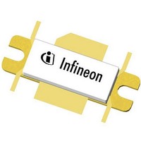
PTFB211503EL V1 R250 Infineon Technologies, PTFB211503EL V1 R250 Datasheet

PTFB211503EL V1 R250
Specifications of PTFB211503EL V1 R250
Related parts for PTFB211503EL V1 R250
PTFB211503EL V1 R250 Summary of contents
Page 1
Confidential, Limited Internal Distribution Thermally-Enhanced High Power RF LDMOS FETs 150 W, 2110 – 2170 MHz Description The PTFB211503EL and PTFB211503FL are thermally-enhanced, 150-watt, LDMOS FETs designed for cellular power amplifier applications in the 2110 to 2170 frequency band. Features ...
Page 2
... Maximum Ratings Parameter Drain-Source Voltage Gate-Source Voltage Junction Temperature Storage Temperature Range Thermal Resistance (T = 70°C, 150 W CW) CASE Ordering Information Type and Version Package Outline PTFB211503EL V1 H-33288-6 PTFB211503EL V1 R250 H-33288-6 PTFB211503FL V2 H-34288-4/2 PTFB211503FL V2 R250 H-34288-4/2 Data Sheet Symbol Conditions Symbol µA V ...
Page 3
Confidential, Limited Internal Distribution Typical Performance (data taken in a production test fixture) Two-carrier WCDMA 3GPP Drive- 1.20 A, 3GPP WCDMA PAR = 8 dB, 10 MHz carrier spacing, BW 3.84 MHz ...
Page 4
Confidential, Limited Internal Distribution Typical Performance (cont.) Two-tone Drive- ƒ = 2170 MHz, ƒ Gain 18 17 Efficiency Output Power, PEP (dBm) Two-tone ...
Page 5
Confidential, Limited Internal Distribution Typical Performance (cont.) CW Performance Gain vs. Output Power ƒ = 2170 MHz ...
Page 6
Confidential, Limited Internal Distribution Broadband Circuit Impedance Z Source G Z Source W Frequency MHz R 2200 2.06 –6.08 2170 2.17 –6.33 2140 2.30 –6.59 2110 2.43 –6.86 2080 2.58 –7.14 See next page for reference circuit information Data Sheet ...
Page 7
PTFB211503EL/FL_INPUT Confidential, Limited Internal Distribution Reference Circuit C801 S1 1000 Out C802 1000 pF R801 C803 R804 1000 pF 1200 Ohm 100 Ohm ...
Page 8
Confidential, Limited Internal Distribution Reference Circuit (cont.) Description DUT PTFB211503EL or PTFB211503FL PCB 0.508 mm [.020"] thick, Electrical Characteristics at 2170 MHz Transmission Electrical Line Characteristics Input 0.095 λ, 54.17 W TL101, TL129 TL102 0.016 λ, 31.24 W 0.026 λ, ...
Page 9
Confidential, Limited Internal Distribution Reference Circuit (cont.) Electrical Characteristics at 2170 MHz Transmission Electrical Line Characteristics Output TL201 (taper) 0.074 λ, 5. 39.51 W 0.010 λ, 4. 5.33 W TL202 (taper) TL203 TL204 TL205 TL206 0.000 ...
Page 10
Confidential, Limited Internal Distribution Reference Circuit (cont.) Circuit Assembly Information Test Fixture Part No. LTN/PTFB211503EF Find Gerber files for this test fixture on the Infineon Web site at RO4350, .030 R804 C801 C802 S3 R805 S1 R803 R101 C101 C103 ...
Page 11
Confidential, Limited Internal Distribution Reference Circuit (cont.) Component Information Component Description Input C101, C102 Chip capacitor C103, C104 Chip capacitor, 4.71 μF C105 Chip capacitor, 0.6 pF C106 Chip capacitor, 2.2 pF C107 Chip capacitor, 8.2 pF C801, ...
Page 12
Confidential, Limited Internal Distribution Package Outline Specifications 4X R1.524 [R.060] 2X R1.626 [R.064] 1.575 [.062] (SPH) 1.016 [.040] Diagram Notes—unless otherwise specified: 1. Interpret dimensions and tolerances per ASME Y14.5M-1994. 2. Primary dimensions are mm. Alternate dimensions are inches. 3. ...
Page 13
Confidential, Limited Internal Distribution Package Outline Specifications 45° X 2.032 [45° X .080] 2X 30° +.381 4X R0.508 -.127 [ ] R.020 +.015 -.005 1.575 [.062] (SPH) 1.016 [.040] Diagram Notes—unless otherwise specified: 1. Interpret dimensions and tolerances per ASME ...
Page 14
... Infineon Technologies components may be used in life-support devices or systems only with the express written approval of Infineon Technologies failure of such components can reasonably be expected to cause the failure of that life-support device or system or to affect the safety or effectiveness of that device or system. Life support devices or systems are intended to be implanted in the human body or to support and/or maintain and sustain and/or protect human life ...


