D4BL-K3 Omron, D4BL-K3 Datasheet
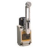
D4BL-K3
Specifications of D4BL-K3


Related parts for D4BL-K3

D4BL-K3 Summary of contents
Page 1
... Note: Contact your sales representative for details on models with safety standard certification. Be sure to read the “Safety Precautions” on page 13 and the “Precautions for All Safety Door Switches”. Operation Key D4BL - Operation Key Type 1: Horizontal mounting 2: Vertical mounting 3: Adjustable mounting (Horizontal) (c)Copyright OMRON Corporation 2007 All Rights Reserved ...
Page 2
... D4BL-2CRB D4BL-2CRB-A D4BL-3CRA D4BL-3CRA-A D4BL-3CRB D4BL-3CRB-A D4BL-1CRG D4BL-1CRG-A D4BL-2CRG D4BL-2CRG-A D4BL-3CRG D4BL-3CRG-A Model D4BL-K1 D4BL-K2 D4BL-K3 (c)Copyright OMRON Corporation 2007 All Rights Reserved. D4BL 1 Without indicator With LED indicator 2NC+ 1NC 2NC+ 1NC (Slow-action) (Slow-action) D4BL-1DRA D4BL-1DRA-A D4BL-1DRB D4BL-1DRB-A D4BL-2DRA D4BL-2DRA-A ...
Page 3
... Certification body EN60947-5-1 (certified direct TÜV Rheinland opening) GS-ET-19 UL UL508 CSA CSA C22.2, No.14 CQC (CCC) GB14048.5 Indicator model AC- 115 V Current (A) Make Break (c)Copyright OMRON Corporation 2007 All Rights Reserved. D4BL Standard File No. R9451050 E76675 LR45746 2003010305073836 Volt-amperes (VA) Make Break 7,200 720 3 ...
Page 4
... The degree of protection is tested using the method specified by the standard (EN60947-5-1). Confirm that sealing properties are sufficient for the operating conditions and environment beforehand. Although the switch box is protected from dust, oil or water penetration, do not use the D4BL in places where dust, oil, water, or chemicals may enter through the key hole on the head, otherwise Switch damage or malfunctioning may occur. ...
Page 5
... Show State with Key Inserted and Lock Engaged) Contact (door open/ Model closed detection Lock monitor and lock monitor) Lock monitor D4BL-@C@@-@ 1NC/1NO+1NC 31 Lock monitor D4BL-@D@@-@ 2NC+1NC 31 Note: The EN-certified direct opening mechanism is indicated by Contact Form 2NC + 2NC (Safety circuit side) (Monitor circuit side) http://www ...
Page 6
... N max. Key extraction force 19.61 N max. Movement before 15 mm max. being locked Total travel 23 mm min. 37.5 Operating Model +1 D4BL-2GRD- Characteristics Key insertion force 19.61 N max. Key extraction force 19.61 N max. Movement before 15 mm max. being locked Total travel 23 mm min. ...
Page 7
... D4BL-K2 Red 53.7 13 25.8 15.6 36 11.8 5.6 4 dia. http://www.ia.omron.com/ D4BL-K3 20 Long mounting hole 7.3 15 Two, 2.65R 5.3 5.3 7.5 2 5.3 dia. 5.3 x 7.3 long mounting hole 40 52.4 5.3 11.9 7.5 20 2.6 (c)Copyright OMRON Corporation 2007 All Rights Reserved. ...
Page 8
... Vertical direction Operation Key insertion radius R ≥ 1000 54.5 min. 58 max. (41) (35) (c)Copyright OMRON Corporation 2007 All Rights Reserved. D4BL D4BL + D4BL-K3 Red Horizontal direction Operation Key insertion radius R ≥ 250 81.5 min. 85 max. (41) (40) (30±0.15) Vertical direction Operation Key insertion radius R ≥ ...
Page 9
... Four terminal plates Two, 7 dia. Two LED indicators (7) (16) 26.8 53.2 57.2 (16) 0.3 5.6 (35) 26.2 (61.2) Connections Internal Circuit Diagram Indicator 10 to 115 VAC/VDC Constant-current diode http://www.ia.omron.com/ 2 10.6 (12.6) Solenoid 24 VDC E1 (+) LED E2 (−) (c)Copyright OMRON Corporation 2007 All Rights Reserved. D4BL 9 ...
Page 10
... Orange: Lights when the solenoid turns ON. Green: Lights when power turns ON. E1 (+) (− Auxiliary circuit (monitor circuit) (c)Copyright OMRON Corporation 2007 All Rights Reserved. D4BL (Power supply side) E1 (+) 32 31 Solenoid E2 (−) LED (orange) LED (green) (Ground side) Safety circuit (Power supply side) ...
Page 11
... Connection Example with OMRON’s G9SA Safety Relay Unit G9SA-321-T@ (24 VAC/VDC) + D4BL-@D@A-@, -@D@B-@ (Mechanical Lock Type) Circuit Diagram (Manual Reset) Lock release signal KM1 KM2 PLC Guard S1 OPEN Stop signal A1 A2 T11 T12 T21 Timing Chart Limit switch S1 Guard Lock ...
Page 12
... G9SA-301 (24 VAC/VDC) + D4BL-@D@G-@ (Solenoid Lock Type) Circuit Diagram (Auto-reset) Lock signal PLC 12 OPEN 11 Operation signal A1 A2 T11 T12 T21 T23 T22 Timing Chart Limit switch S1 Guard Lock Safety-door Switch S2 Operation signal Lock signal K1 and K2 (NC) K1 and K2 (NO) KM1 and KM2 ...
Page 13
... Four, M5 switch-mounting screw Auxiliary Release Key The auxiliary release key is used to unlock the D4BL in case of emergency or in case the power supply to the D4BL fails. Use the enclosed Release Key to change the lock from LOCK to UNLOCK so that the lock will be released and the door can be opened ...
Page 14
... Operation Key Mounting Holes D4BL-K1 Two, M5 20±0.1 D4BL-K2 Two, M5 40±0.1 D4BL-K3 Two, M5 30±0.1 Operation Key The D4BL is provided with a shock-absorbing damper to protect the D4BL from damage that may result from dropping the D4BL during transportation. Be sure to remove the damper after mounting the D4BL ...
Page 15
... Properly attach and securely tighten the provided conduit cap to the unused conduit opening to the suitable tightening torque when wiring the D4BL. http://www.ia.omron.com/ Cable Connection Example 1. Connect the wires to the terminals in the order shown below for wiring efficiency. Tighten each wired terminal clockwise to a torque of 0.59 to 0.78 N· ...
Page 16
... Injury may result. Do not drop the Switch. Doing so may prevent the Switch from functioning to its full capability. Do not under any circumstances disassemble or modify the Switch. Doing so may cause malfunction. (c)Copyright OMRON Corporation 2007 All Rights Reserved. C-1 ...
Page 17
... Key may damage the Switch or affect machine safety. Do not operate the Switch with anything other than the special OMRON Operation Key, otherwise the Switch may break or the safety of the system may not be maintained. Do not impose excessive force on the Operation Key while the Key is inserted into the Switch or drop the Switch with the Operation Key inserted ...
Page 18
... Do not impose shock or vibration on the Actuator while it is fully pressed. Otherwise, the Actuator will partially abrade and an actuation failure may result. t (c)Copyright OMRON Corporation 2007 All Rights Reserved. C-3 ...
Page 19
... Switch. When complying with EN certified ratings, use a 10-A IEC 60269- compliant fuse. (c)Copyright OMRON Corporation 2007 All Rights Reserved. Precautions for All Switches Incorrect Power Connection Example ...
Page 20
... Unusable range 0.1 (c)Copyright OMRON Corporation 2007 All Rights Reserved. Precautions for All Switches when it 3 Element selection Use the following as guides for C and R values 0.5 F per contact current ( per contact voltage (V) These values depend on various factors, including the load ...
Page 21
... When storing the Switch, make sure that the location is free of corrosive gas, such as H does not have a high temperature or humidity. Be sure to inspect the Switch before use if it has been stored for three months or more. (c)Copyright OMRON Corporation 2007 All Rights Reserved. Precautions for All Switches ), ammonium gas (NH ), nitric gas (HNO high temperature and humidity ...
Page 22
... Contact welding due to an incorrectly connected power source. Foreign materials or oil penetrated into the contact area. (c)Copyright OMRON Corporation 2007 All Rights Reserved. Precautions for All Switches Remedy Change the design of the dog or cam and smooth the contacting surface of the cam. ...
Page 23
... Terminal screw screw Terminal Terminal Incorrect Wiring Incorrect Crimped location facing down Lead Crimp terminal Terminal Terminal screw screw Terminal Terminal Too close to maintain dielectric strength http://www.ia.omron.com/ Correct (c)Copyright OMRON Corporation 2007 All Rights Reserved. Precautions for All Switches C-8 ...
Page 24
... When transferring devices and equipment, be sure to keep one copy of the Operating Manual and pack another copy with the device or equipment so the person receiving it will have no problem operating it. • Related International Standards: ISO 12100 Basic Concepts, General Principles for Design IEC 61508 Functional Safety of Electrical/Electronic/Programmable Electronic Safety-related Systems http://www.ia.omron.com/ WARNING (c)Copyright OMRON Corporation 2007 All Rights Reserved. ...
Page 25
... Please read and understand this catalog before purchasing the products. Please consult your OMRON representative if you have any questions or comments. WARRANTY OMRON's exclusive warranty is that the products are free from defects in materials and workmanship for a period of one year (or other period if specifi ed) from date of sale by OMRON. OMRON MAKES NO WARRANTY OR REPRESENTATION, EXPRESS OR IMPLIED, REGARDING NON-INFRINGEMENT, MERCHANTABILITY, OR FITNESS FOR PARTICULAR PURPOSE OF THE PRODUCTS ...