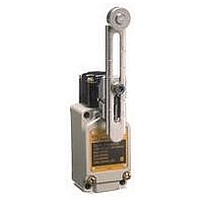
D4BL-K3 Omron, D4BL-K3 Datasheet - Page 13

D4BL-K3
Manufacturer Part Number
D4BL-K3
Description
Contact OSTI For Purchase
Manufacturer
Omron
Type
Safety-Door Switchr
Series
D4BLr
Specifications of D4BL-K3
Contact Form
DPDT
Contact Rating
10 Amps
Actuator
Plunger
Operating Force
19.61 N
Termination Style
Wire
Color
Red
Mounting Style
Screw
Lead Free Status / RoHS Status
Lead free / RoHS Compliant
For Use With
D4BL Guard Lock Safety Door Switches
Lead Free Status / Rohs Status
Lead free / RoHS Compliant
Other names
Q2025725A
Safety Precautions
Refer to the “Precautions for All Switches” and “Precautions for All Safety Door Switches”.
Stopper Installation
Do not use a Switch as a stopper. Be sure to install a stopper as
shown in the following illustration when mounting the Switch so that
the Operation Key is within 0.5 to 5 mm of the set zone.
Do not subject the Switch to a shock that exceeds the Switch's shock
resistance of 1,000 m/s
Injury may occasionally occur. Always check to make
sure that the safety functions operate correctly before
using the machine. The safety functions may not operate
correctly because of wiring mistakes, setting mistakes,
or Switch malfunction, causing some machines to
continue operating in situations where they should be
stopped.
Injury may occasionally occur. If the machine is used
with the release key in the UNLOCK position, the
electromagnetic lock may not operate, causing some
machines to continue operating in situations where they
should be stopped. Be sure to put the release key in the
LOCK position before using the machine. Also, check
the condition of the lock and safety circuits.
Injury may occasionally occur. When the
electromagnetic lock function or Switch function is
damaged, some machines may continue operating in
situations where they should be stopped. Do not use the
electromagnetic lock function of the Switch in place of a
door lock. Always provide a lock separate from the
Switch, attach a warning seal to prevent people from
using excessive force to open the door when it is locked,
or provide an indicator lamp to show the locked/unlocked
status of the door.
Correct
Incorrect
Do not use the Switch submersed in oil or water or in locations
continuously subject to splashes of oil or water. Doing so may
result in oil or water entering the Switch. (The IP67 degree of
protection of the Switch specifies the amount of water penetration
after the Switch is submerged in water for a certain period of time.)
Always attach the cover after completing wiring and before using
the Switch. Also, do not turn ON the Switch with the cover open.
Doing so may result in electric shock.
Make sure the Switch is mounted securely to prevent it from falling
off. Otherwise injury may result.
Set zone
Gap
Precautions for Safe Use
Switch
http://www.ia.omron.com/
Stopper
2
.
DANGER
Incorrect
Correct
Appropriate Tightening Torque
Loose screws may result in malfunction. Tighten the screws to the
specified torques.
* Use M5 screws. Apply a torque of 4.90 to 5.88 N·m for an
Auxiliary Release Key
Solenoid Lock Models
The solenoid lock locks the door only when power is supplied to the
solenoid. Therefore, the door will be unlocked if the power supply to
the solenoid stops. Therefore, do not use solenoid lock models for
machines that may be operating and dangerous even after the
machine stops operating.
No.
Allen-head bolt. For a pan head screw, apply a torque of 2.35 to
2.75 N·m
2. Four, M4 cover-mounting
1
2
3
4
5
6
7
5. Two, M5 Operation Key mounting screw
The auxiliary release key is used to unlock the D4BL in case of
emergency or in case the power supply to the D4BL fails.
Use the enclosed Release Key to change the lock from LOCK to
UNLOCK so that the lock will be released and the door can be
opened. (Applies only to mechanical locks.)
Whenever the lock has been changed to UNLOCK, always return
it to LOCK before using the Switch.
Do not use the auxiliary release key to start or stop machines.
Make sure that the auxiliary release key is kept with the person in
charge.
To prevent the auxiliary release key from being handled carelessly
by unauthorized people, seal the auxiliary release key with sealing
wax and the provided seal cap to ensure IP67.
Before attaching the cover to the D4BL, make sure that the
auxiliary release key position is set to LOCK.
screw
6. Conduit
(c)Copyright OMRON Corporation 2007 All Rights Reserved.
M3.5 terminal screw
(including terminal screw)
Cover mounting screw
Head mounting screw
M5 body mounting screw *
Operation Key mounting screw
Connector
Cap screw
Precautions for Correct Use
UNLOCK
4. Four, M5
switch-mounting screw
Type
LOCK
Auxiliary
release key
3. Four, M3.5 head-mounting screw
7. Conduit cap
0.59 to 0.78 N·m
1.18 to 1.37 N·m
0.78 to 0.98 N·m
4.90 to 5.88 N·m
2.35 to 2.75 N·m
1.77 to 2.16 N·m
1.27 to 1.67 N·m
Appropriate
tightening
torque
D4BL
13


