NTJD1155LT1G ON Semiconductor, NTJD1155LT1G Datasheet - Page 2
NTJD1155LT1G
Manufacturer Part Number
NTJD1155LT1G
Description
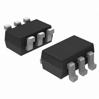
MOSFET N/P-CH 8V 1.3A SOT-363
Manufacturer
ON Semiconductor
Datasheet
1.NTJD1155LT1G.pdf
(5 pages)
Specifications of NTJD1155LT1G
Fet Type
N and P-Channel
Fet Feature
Standard
Rds On (max) @ Id, Vgs
175 mOhm @ 1.2A, 4.5V
Drain To Source Voltage (vdss)
8V
Current - Continuous Drain (id) @ 25° C
1.3A
Vgs(th) (max) @ Id
1V @ 250µA
Power - Max
400mW
Mounting Type
Surface Mount
Package / Case
SC-70-6, SC-88, SOT-363
Configuration
Dual
Transistor Polarity
N and P-Channel
Resistance Drain-source Rds (on)
0.32 Ohm @ P Channel
Drain-source Breakdown Voltage
8 V @ P Channel
Gate-source Breakdown Voltage
8 V @ N Channel
Continuous Drain Current
+/- 1.3 A
Power Dissipation
400 mW
Maximum Operating Temperature
+ 150 C
Mounting Style
SMD/SMT
Minimum Operating Temperature
- 55 C
Lead Free Status / RoHS Status
Lead free / RoHS Compliant
Gate Charge (qg) @ Vgs
-
Lead Free Status / Rohs Status
Lead free / RoHS Compliant
Other names
NTJD1155LT1GOSTR
Available stocks
Company
Part Number
Manufacturer
Quantity
Price
Company:

Part Number:
NTJD1155LT1G
Manufacturer:
ON
Quantity:
18 000
Company:
Part Number:
NTJD1155LT1G
Manufacturer:
ON
Quantity:
30 000
Part Number:
NTJD1155LT1G
Manufacturer:
ON/安森美
Quantity:
20 000


*Minimum R1 value should be at least 10 x R2 to ensure Q1 turn−on.
ELECTRICAL CHARACTERISTICS
OFF CHARACTERISTICS
ON CHARACTERISTICS
Q2 Drain−to−Source Breakdown Voltage
Forward Leakage Current
Q1 Gate−to−Source Leakage Current
Q1 Diode Forward On−Voltage
ON/OFF Voltage
Q1 Gate Threshold Voltage
Input Voltage
Q2 Drain−to−Source On Resistance
Load Current
Characteristic
Components
C
O
R1
R2
C1
, C
I
ON/OFF
V
R2
IN
C
I
(T
R1
J
Pullup Resistor
Optional Slew−Rate Control
Output Capacitance
Optional In−Rush Current Control
= 25°C unless otherwise noted)
Symbol
V
V
R
Figure 1. Load Switch Application
ON/OFF
GS1(th)
I
DS(on)
V
V
GSS
V
I
FL
I
SD
IN
IN
L
4
6
5
http://onsemi.com
Q1
Description
Q2
V
V
ON/OFF
V
V
V
V
V
V
DS2
V
DROP
DROP
GS1
DS1
I
GS1
GS1
S
GS2
2
1
R2
= −0.4 A, V
= −8.0 V
V
V
Test Condition
= 0 V,
= 0 V, V
= V
= V
= 0 V, I
ON/OFF
ON/OFF
= 1.5 V
≤ 0.2 V, V
≤ 0.3 V, V
DS1
DS1
, I
, I
2,3
D2
GS1
= 1.5 V
= 1.5 V
D
D
GS1
6
= 250 mA
= 250 mA
= 250 mA
IN
IN
= ±8.0 V
C
T
V
V
V
= 5.0 V,
= 2.5 V,
= 0 V
O
T
I
I
I
J
IN
L
IN
L
IN
L
C1
J
= 125°C
= 1.2 A
= 1.0 A
= 0.7 A
= 25°C
= 4.5 V
= 2.5 V
= 1.8 V
Typical 10 kW to 1.0 MW*
Typical 0 to 100 kW*
Usually < 1.0 mF
Typical ≤ 1000 pF
LOAD
V
GND
−8.0
Min
OUT
1.5
0.4
1.8
1.0
1.0
−0.8
Typ
130
170
260
Values
±100
Max
−1.1
175
220
320
1.0
8.0
1.0
8.0
10
Unit
mW
nA
mA
V
V
V
V
V
A
Related parts for NTJD1155LT1G
Image
Part Number
Description
Manufacturer
Datasheet
Request
R

Part Number:
Description:
ON Semiconductor [VOLTAGE REGULATOR]
Manufacturer:
ON Semiconductor
Datasheet:
Part Number:
Description:
357-036-542-201 CARDEDGE 36POS DL .156 BLK LOPRO
Manufacturer:
ON Semiconductor
Datasheet:
Part Number:
Description:
357-036-542-201 CARDEDGE 36POS DL .156 BLK LOPRO
Manufacturer:
ON Semiconductor
Datasheet:
Part Number:
Description:
357-036-542-201 CARDEDGE 36POS DL .156 BLK LOPRO
Manufacturer:
ON Semiconductor
Datasheet:
Part Number:
Description:
357-036-542-201 CARDEDGE 36POS DL .156 BLK LOPRO
Manufacturer:
ON Semiconductor
Datasheet:
Part Number:
Description:
357-036-542-201 CARDEDGE 36POS DL .156 BLK LOPRO
Manufacturer:
ON Semiconductor
Datasheet:
Part Number:
Description:
357-036-542-201 CARDEDGE 36POS DL .156 BLK LOPRO
Manufacturer:
ON Semiconductor
Datasheet:
Part Number:
Description:
357-036-542-201 CARDEDGE 36POS DL .156 BLK LOPRO
Manufacturer:
ON Semiconductor
Datasheet:
Part Number:
Description:
357-036-542-201 CARDEDGE 36POS DL .156 BLK LOPRO
Manufacturer:
ON Semiconductor
Datasheet:
Part Number:
Description:
357-036-542-201 CARDEDGE 36POS DL .156 BLK LOPRO
Manufacturer:
ON Semiconductor
Datasheet:
Part Number:
Description:
357-036-542-201 CARDEDGE 36POS DL .156 BLK LOPRO
Manufacturer:
ON Semiconductor
Datasheet:
Part Number:
Description:
Manufacturer:
ON Semiconductor
Datasheet:
Part Number:
Description:
Manufacturer:
ON Semiconductor
Datasheet:
Part Number:
Description:
Manufacturer:
ON Semiconductor
Datasheet: