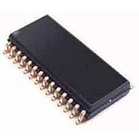
CS8420-DSR Cirrus Logic Inc, CS8420-DSR Datasheet - Page 52

CS8420-DSR
Manufacturer Part Number
CS8420-DSR
Description
Audio DSPs IC Digital Audio Sample Rate Convertr
Manufacturer
Cirrus Logic Inc
Datasheet
1.CS8420-CSZ.pdf
(94 pages)
Specifications of CS8420-DSR
Lead Free Status / RoHS Status
Lead free / RoHS Compliant
CS8420
FILT - PLL Loop Filter *
An RC network should be connected between this pin and ground. Recommended schematic and component val-
ues are given in
“PLL Filter” on page
87.
Overall Device Control:
H/S - Hardware or Software Control Mode Select *
The H/S pin determines the method of controlling the operation of the CS8420, and the method of accessing CS
and U data. In Software mode, device control and CS and U data access is primarily via the control port, using a
microcontroller. In Hardware mode, alternate modes and access to CS and U data is provided by pins. This pin
should be permanently tied to VD+ or DGND.
RST - Reset Input *
When RST is low, the CS8420 enters a low-power mode and all internal states are reset. On initial power-up, RST
must be held low until the power supply is stable, and all input clocks are stable in frequency and phase. This is
particularly true in Hardware mode with multiple CS8420 devices, where synchronization between devices is impor-
tant.
INT - Interrupt Output
The INT output pin indicates errors and key events during the operation of the CS8420. All bits affecting INT are
maskable via control registers. The condition(s) that initiated interrupt are readable via a control register. The polarity
of the INT output, as well as selection of a standard or open-drain output, is set via a control register. Once set true,
the INT pin goes false only after the interrupt status registers have been read, and the interrupt status bits have re-
turned to zero.
Audio Input Interface:
SDIN - Serial Audio Input Port Data Input
Audio data serial input pin.
ISCLK - Serial Audio Input Port Bit Clock Input or Output
Serial bit clock for audio data on the SDIN pin.
ILRCK - Serial Audio Input Port Left/Right Clock Input or Output
Word rate clock for the audio data on the SDIN pin. The frequency will be at the input sample rate (Fsi)
AES3/SPDIF Receiver Interface:
RXP, RXN - Differential Line Receiver Inputs
Differential line receiver inputs, carrying AES3-type data.
RERR - Receiver Error Indicator
When high, indicates a problem with the operation of the AES3 receiver. The status of this pin is updated once per
sub-frame of incoming AES3 data. Conditions that can cause RERR to go high are: validity, parity error, bi-phase
coding error, confidence, QCRC and CCRC errors, as well as loss of lock in the PLL. Optionally, each condition may
be masked from affecting the RERR pin using the Receiver Error Mask Register. The RERR pin tracks the status
of the unmasked errors: the pin goes high as soon as an unmasked error occurs and goes low immediately when
all unmasked errors go away.
52
DS245F4


